What Is Microdieseling?
Microdieseling occurs when entrained air moves from low-pressure zones to high-pressure in a lubrication system, reaching localized temperatures above 1000°C and carbonizing the oil.
The term microdieseling got its name from the diesel engine. In a diesel engine, there is usually a rapid compression of air, which leads to an explosion. Similarly, during the degradation of an oil, there is firstly the introduction of entrained air into the oil. Typically, this entrained air moves from a low-pressure zone to a high-pressure zone.
During this transition, the entrained air produces localized temperatures above 1,000°C. While the trapped air is at this temperature, its outer surface is in contact with the lubricant.
As the lubricant around the bubble is exposed to this temperature, it becomes carbonized. The oil quickly darkens and produces carbon deposits since many entrained air bubbles undergo this process.
Eventually, the bubble will implode (or cause a small explosion). This is where the term “microdieseling effect” comes from, as the bubble undergoes a similar process to that of the diesel engine.
During microdieseling, the air will compress rapidly and eventually produce an explosion similar to the compression of air to create an explosion in a diesel engine. However, microdieseling has one more step, which heavily influences the type of deposits created.
The Effects of Microdieseling
When microdieseling occurs, its final results can differ depending on the conditions experienced in the system. The entrained air will typically experience a low flash point (there is no need to worry about a fire risk here).
However, the bubble can either undergo a high or low implosion pressure. The type of implosion pressure makes a significant difference in the kind of deposit that is formed.
When the bubble undergoes a low flash point with a high implosion pressure, this is similar to a quick explosion. We can compare this to a bomb exploding.
In this case, ignition products of incomplete combustion form, such as soot, tars, and sludge. If we have an explosion, we will also have incomplete combustion of the items in the area, such as items that did not fully explode.
On the other hand, if the bubble undergoes a low flashpoint with a low implosion pressure, it experiences adiabatic compressive thermal heating. This will result in varnish insolubles such as coke, tars, and resins. Unlike a quick explosion, these products fully degrade to form these deposits.
Confirming The Presence of Microdieseling
Based on the types of deposits that form after microdieseling, it may be challenging to determine whether these are related to this mechanism. However, there is one tell-tale sign which usually takes place during microdieseling. This is cavitation.
Although cavitation is a mechanism experienced by pumps, it can also be seen in lubrication systems.
During microdieseling, there are small explosions of trapped air, which can significantly impact the internal surface of the equipment. As such, operators usually notice some form of cavitation in systems experiencing microdieseling.
Some laboratory tests can be employed to confirm the presence of the types of deposits. The FTIR (Fourier Transform Infrared) and QSA® (Quantitative Spectrophotometric Analysis) are helpful tools for confirming the presence of sludge, soot, tars, or resins in the oil.
Getting To the Root Cause
Now that the basics of microdieseling are covered, we need to identify if it is occurring in our system. The best way to figure this out is by using a logic tree and asking the right questions. We can start to build the logic tree by asking “How could?” instead of “Why?”. This is the beginning of the tree, as shown in Figure 1 below.
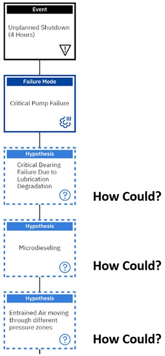
Figure 1: First Step of the Microdieseling Logic Tree
In this first part, we assume we are investigating an unplanned shutdown where a critical pump failure was the failure mode. We ask the question, “How could a critical pump have a failure?“. In this case, we are following the lubrication failure path (in a real investigation, there may be more than one failure mode).
As such, we hypothesize that there was a critical bearing failure due to lubrication degradation. This is where the question of “How could a critical bearing failure occur due to lubricant degradation?” is critical.
In a real investigation, several different degradation mechanisms can be investigated. However, for this example, we will investigate the degradation mechanism of microdieseling.
We ask the famous question, “How could microdieseling occur?“. Based on the information we gathered earlier in this article, we know that the main reason for microdieseling is the presence of entrained air moving through different pressure zones.
Hence, this becomes our next hypothesis, and we must again ask the question, “How could entrained air that moves through different pressure ones exist in our system?” which is investigated in Figure 2 below.
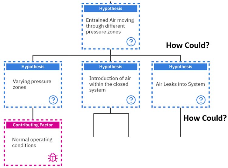
Figure 2: Second Part of the Microdieseling Tree
The second way occurs if air is introduced within the closed system. On the other hand, the third way involves having air leaks into the system. These will now be investigated by asking our famous “How could?” question.
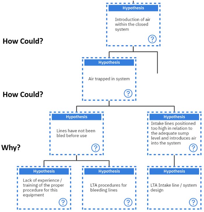
Figure 3: Investigating ‘The Introduction of Air Into a Closed System’ with the Hypothesis of ‘Air Trapped In the System’
We must investigate “How could air be introduced into a closed system?“. The first hypothesis which comes to mind is if we have air trapped in the system. As such, the air is already in the system, so it has not entered the closed system.
“How could air be trapped in the system?”. When thinking about a closed system, there are two main ways in which air can be trapped. If the lines were not bled before being used, any air in the lines can become trapped and result in entrained air in the system, or if the intake lines were positioned too high in relation to the adequate sump level to introduce air into the system.
At this time, a decision had to be made on whether to bleed the lines; this is where the line of questioning changes from “How could?” to “Why?”. In this step, we move from a physical root to a human or systemic root.
When asked, “Why were the lines not bled?” there are two general answers. The personnel carrying out this task lacked the experience or training for the proper procedure. In this case, we can drill down even further to explore why they did not have the proper expertise, but we will stop here as this is part of the investigation.
Or, there were inadequate (Less Than Adequate – LTA) procedures for bleeding the lines. This can be related to a systemic root where questions such as “Do the employees have access to the manuals?” or “Were these procedures detailed in the scope of works?” will be asked.
Another way air can be trapped in a closed system and lead to microdieseling is if air is being introduced into the system due to the positioning of the intake lines. If the sump levels are not properly aligned with the intake lines, air can enter the system. In this case, the system may have a design error, or the lines were not installed correctly during the initial setup.
These are just some of how air can be trapped in the system. Another hypothesis explores how air could be introduced into a closed system, as shown below in Figure 4.
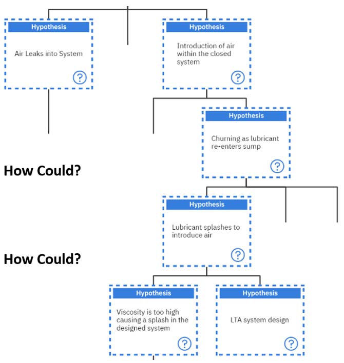
Figure 4: Investigating ‘The Introduction of Air into a Closed System’ with the Hypothesis of ‘Churning as the Lubricant Re-enters the Sump’
Another way in which air can be introduced into the system is if the lubricant churns when it is re-entering the sump. There are a couple of ways in which this can happen.
The first way this can occur is if the lubricant creates a splash upon re-entering and introduces air into the system. Typically, this can happen if the lubricant viscosity is too high, causing a splash in a system that was not designed for it to splash or if the system was not adequately designed.
If we further investigate the hypothesis that the lubricant’s viscosity was too high, we can decipher the following in Figure 5.
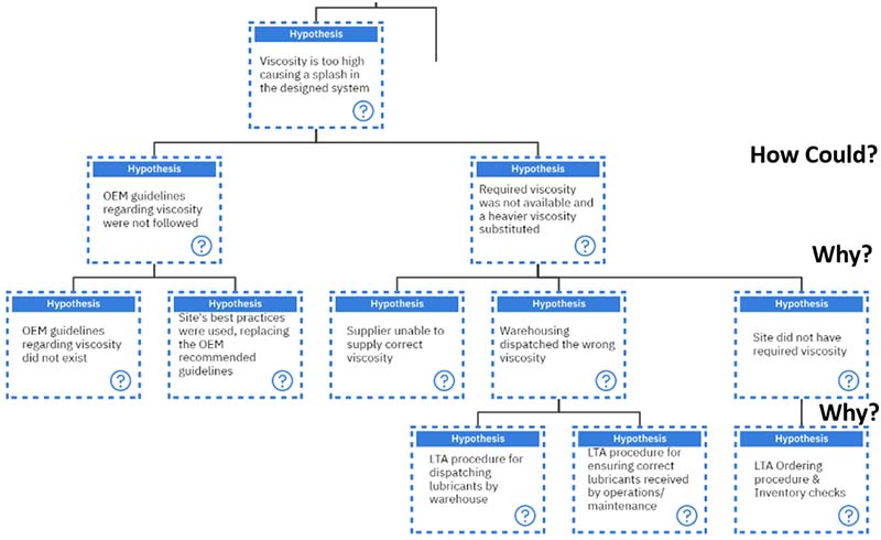
Figure 5: Investigating If the Viscosity Is Too High, Causing a Splash In The System
The “How could?” question can lead us to two hypotheses when investigating whether the viscosity was too high and causing microdieseling. Either the OEM guidelines regarding viscosity were not followed, or the required viscosity was unavailable, and a heavier oil viscosity was substituted.
If we follow the hypothesis of the OEM guidelines not being followed, clearly, a decision was being made here. As such, the line of questioning changes from “How could?” to “Why?”.
There are two general reasons why the OEM guidelines would not be followed. The first reason is that the OEM guidelines do not exist. This is sometimes the case as OEMs may not always publish the required viscosity for the equipment and may say a general statement such as, “Use hydraulic oil.”
In these cases, it would be wise to contact the OEM directly and ask for guidance on choosing the most appropriate viscosity based on your system’s operating and environmental conditions.
The second reason for not following the OEM guidelines (which are more common in the industry) is that the site’s best practices were used instead. For instance, if only ISO 46 hydraulic oil is used on all the pumps, then it may be assumed that this pump should utilize that viscosity when that may not be true.
On the other hand, if the required viscosity was not available and a higher viscosity was substituted, another decision was also made here. Thus, the line of questioning changes again from “How could?” to “Why?”.
Not having the required viscosity is another common occurrence in the industry, and this may span three reasons. Either the supplier was unable to supply the correct viscosity, so the supplier should conduct their own root cause analysis to determine where their challenges lie.
Or, Warehousing dispatched the wrong viscosity, which can occur if there is an inadequate procedure for dispatching lubricants or an inadequate procedure for ensuring the correct lubricant is received by operations or maintenance. In these cases, the errors are more systematic as there are no proper checks to ensure the product is dispatched or received correctly.
Another reason the required viscosity is unavailable is if the site did not have the required viscosity at its location. This can be a result of inadequate ordering procedures or inventory checks such that they are not aware of the quantity of lubricants they physically have or how much they need.
Two other hypotheses should be investigated regarding the churning of the lubricant as it re-enters the sump, as seen in Figure 6.
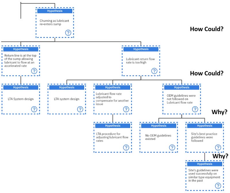
Figure 6: Continuing the Investigation of ‘Churning As the Lubricant Re-enters the Sump’
There are three main reasons for a lubricant to churn as it re-enters the sump. The first reason with the viscosity being too high was covered above. The second reason involves the placement of the return line to the sump.
If this is too high or at a steep angle, it can allow the lubricant to flow at an accelerated rate back into the sump, resulting in churning. This can result from a poorly designed system, which is a systemic cause.
On the other hand, if the actual return flow rate of the lubricant has been set to a higher value, this can also cause churning in the sump. No decisions have yet been made, so the line of questioning remains at “How could?”.
This leads to three new hypotheses: the first can be an inadequate system design. This aspect of the system may have been overlooked by the designers initially, and they were unaware of the results of this increased flow rate back to the sump.
Another hypothesis can suggest that the lubricant flow rate was adjusted to compensate for some other issue in the system. Typically, this is done to allow for faster cooling in certain areas, which can help maintain the system temperatures and avoid overheating. In this case, there may not have been an adequate procedure for adjusting the lubricant flow rates, which reverts to a systemic microdieseling cause.
The last hypothesis centers on the OEM guidelines about the lubricant flow rate not being followed. In this instance, a decision was made, so the question becomes, “Why?” instead of “How could?”.
Two main reasons exist why the OEM guidelines weren’t followed. The first is that the OEM guidelines do not exist. This can be very common as not all OEMs may have designed the entire system.
The other reason is that the site’s best practices were followed. Usually, this is the case when these site’s practices were used in the past without any challenges to the equipment. This is another systemic cause that can be noted in this logic tree.
Reverting to the top of the tree again, one hypothesis investigated whether “Air leaks into the system” could result from entrained air in the system. This was the last hypothesis under the main hypothesis, as seen below and in Figure 7:
Entrained air moving through different pressure zones can lead to the introduction of air within the closed system, varying pressure zones, air leaks into the system
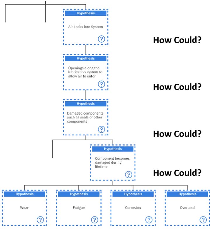
Figure 7: Investigating Air Leaks Into the System
When we think about air leaks into the system, there is one main way this can occur. There must be an opening along the lubrication system, which allows air to enter the system. Now, we ask, “How could there be an opening?”.
One of the main ways for an opening to occur along a closed system is that there is a damaged component, such as a seal or some other component. Again, “How could we have a damaged component?” arises.
The first hypothesis is that the component has been damaged during its lifetime. The investigation has veered away from the lubricant aspect and dived heavily into the mechanical area. A component can be physically damaged in four main ways: wear, fatigue, corrosion, or overload.
These will not be investigated further in this example, but in the actual microdieseling investigation, an expert should assess which failures occurred and how. This will give more depth to the tree and provide more root causes.
The second way we can have a damaged component is if it was defective in the first place; this is shown in Figure 8 below.
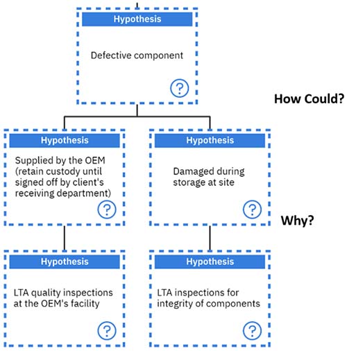
Figure 8: Investigating a Defective Component
If the OEM supplied it, they need to perform quality inspections before any components leave their facility. This is something that a lot of the larger OEMs may enforce, so it would be a good idea to contact them and look at their past inspections during your investigation.
On the other hand, the component can also become damaged while on the customer’s site. There may be inadequate inspections to verify the integrity of the components before they are installed into the equipment. This is yet another systemic root cause that we have uncovered.
The Final Root Causes
From the above exercise, we can determine many root causes when microdieseling is involved. The essential factor to remember is to investigate why the air gets entrained into the system, which has varying pressures.
The line of questioning is critical in uncovering exactly “How could?” this happen, based on the facts of the system and not opinions. Some oil analysis tests can help determine the presence of microdieseling, but we need to get to the root causes before the issue is solved.
This is a list of the suggested root causes for this investigation, which will differ based on varying equipment (where LTA – Less Than Adequate):
- Defective components
- LTA quality inspections at OEM facility
- LTA inspections for the integrity of components
- Viscosity too high, causing a splash in the designed system
- OEM guidelines regarding viscosity did not exist
- The site’s best practices were used, replacing OEM-recommended guidelines
- Supplier unable to supply correct viscosity
- Warehousing dispatched the wrong viscosity
- LTA procedure for dispatching lubricants by warehouse
- LTA procedure for ensuring correct lubricants received by operations/maintenance
- The site did not have the available viscosity
- LTA ordering procedure & Inventory Checks
- Lubricant return flow rate is too high
- Lubricant flow rate adjusted to compensate for another issue
- LTA procedure for adjusting lubricant flow rate
- OEM guidelines were not followed regarding lubricant flow rate
- No OEM guidelines existed
- The site’s guidelines were used successfully on similar types of equipment in the past
- LTA system design
- Lubricant flow rate adjusted to compensate for another issue
- Air trapped in the system
- Lines have not been bled before use
- Lack of experience/training in the proper procedure for this equipment
- LTA procedures for bleeding lines
- Intake lines positioned too high in relation to the adequate sump level and introduces air into the system
- LTA Intake line/system design
- Lines have not been bled before use
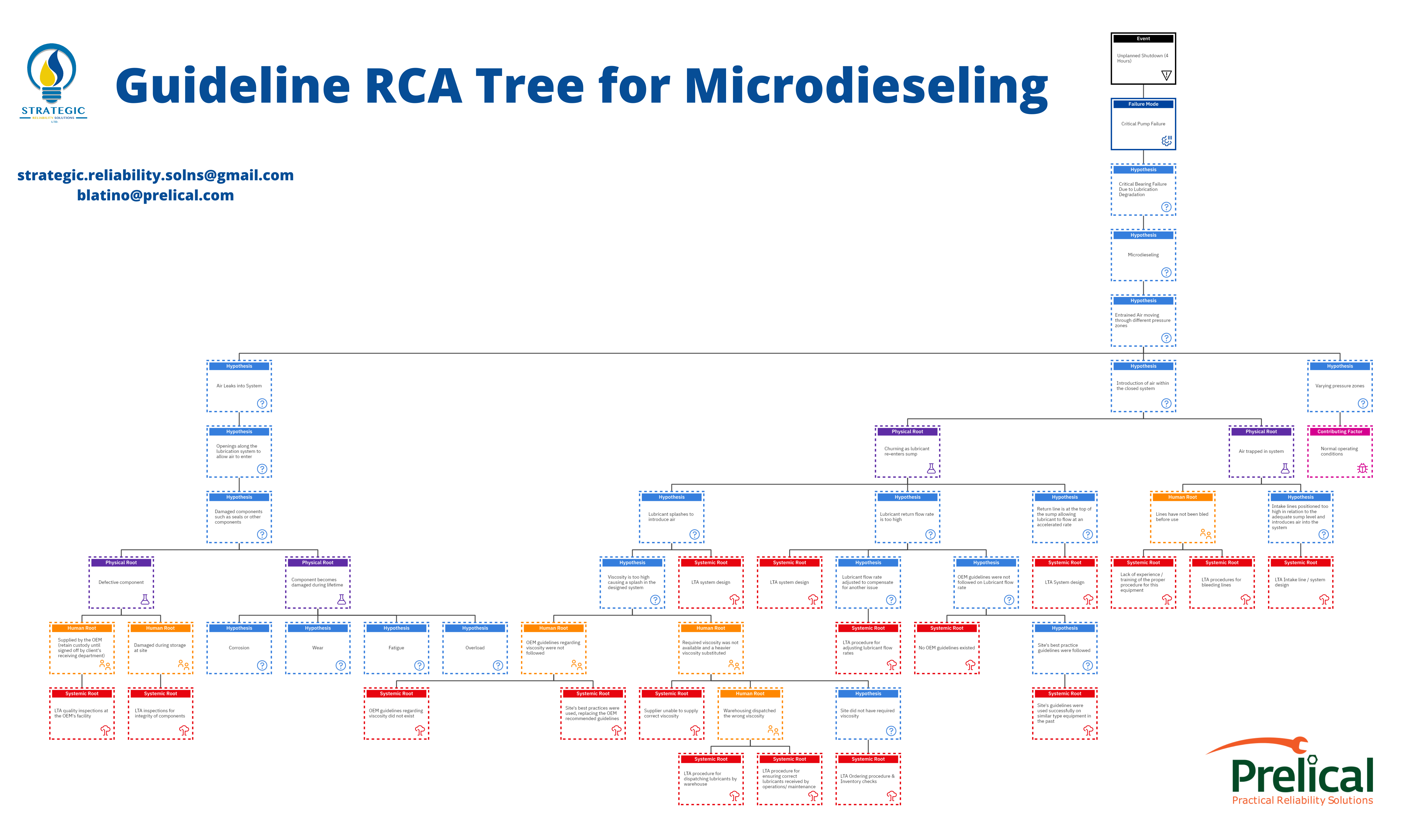
Here’s a handy Guideline RCA Tree for Microdieseling.
References:
Latino, Bob, Sanya Mathura. 2021. Lubrication Degradation – Getting into the Root Causes. CRC Press, Taylor & Francis.