Condition monitoring sensors for lubricants have been an established technology for numerous decades, playing a vital role in safeguarding some of the most essential machinery worldwide, including their incorporation into certain premium automotive models.
However, it is somewhat paradoxical that lubricants within rotary machines, such as turbines and compressors—equipment fundamental to electricity generation and numerous chemical and industrial operations—rarely utilize remote sensing for condition monitoring.
This discrepancy can be attributed to two primary factors. First, the longevity of turbine oils, particularly within older steam or hydroelectric turbines, has deemed quarterly oil analysis sufficient for tracking condition trends.
Second, the performance of sensors available to these applications thus far has demonstrated inadequate correlation with analytical laboratory results.
But the landscape is evolving. Modern gas turbines operate at higher temperatures, imposing unprecedented thermal stress on their lubricants. Compressor systems present an even more demanding scenario for turbine oils, contending with thermal challenges, contamination from external gases, and, in some instances, exceedingly high operational speeds.
Concurrently, there is a burgeoning requirement for remote monitoring capabilities that minimize the necessity for physical, on-site maintenance. Against this backdrop, the imperative for real-time oil condition monitoring is intensifying.
This document examines a new real-time turbine oil monitoring development that employs infrared spectroscopy. It further elucidates the capacity of this technological advancement to meet the escalating demand for sophisticated sensors in this space.
Why Turbines and Turbine Oils Fail
Oil condition monitoring serves three primary technical objectives:
- Monitoring Lubricant Degradation Trends: This involves systematically tracking the degradation and aging process of the lubricant over time, which is crucial for maintaining optimal lubrication performance.
- Detecting Machinery Health Deterioration: The analysis aims to identify any signs of machinery wear or failure, which can be inferred from changes in the lubricant’s properties or composition.
- Quantifying Contaminant Levels: This includes the measurement of both external contaminants (such as dirt and water) and internally generated by-products (like wear metals and varnish). These contaminants can significantly impact the functioning and longevity of the machinery.
Given these purposes, it becomes clear that a thorough understanding of both turbine operation and the failure mechanisms of turbine oils is fundamental to effectively determining oil condition monitoring strategies.
Turbine Failure Modes
The most common modes of failure for turbines[1],[2],[3] are:
- Creep and Fatigue – which are caused by high temperatures and stress cycles. These can cause deformation, cracking, loss of efficiency, weakening of metal components, and rupture of the steam turbine components.
- Oxidation and corrosion are the chemical reactions of metal components with oxygen and other environmental substances. Oxidation and corrosion can cause pitting, scaling, and erosion of the turbine blades and other parts, reducing their strength and durability.
- Erosion is metal components’ physical wear and tear by abrasive particles or fluids. Erosion can cause material loss, roughness, and damage to the turbine blades and other parts, affecting their aerodynamics and performance.
- Steam-path distortion and/or blade/nozzle mechanical damage is caused by foreign-object damage, solid-particle erosion, cracking, and moisture erosion. These can affect a steam turbine’s flow, efficiency, and performance.
- Babbitt bearing failures, which are caused by babbitt fatigue, babbitt wiping, babbitt flow, foreign particle damage, varnish build-up, electrostatic discharge damage, electromagnetic discharge damage, oil burn, loss of bond, chemical attack, pivot wear, unloaded pad flutter, and cavitation damage. These can affect the alignment, stability, and vibration of the turbine.
Most turbine failure modes are not readily identifiable through oil sensor analysis, except for bearing health assessment. To effectively monitor the condition of turbine bearings, it is essential to employ sensors, including:
- Temperature Probes: These devices measure the temperature of the bearing, which is a critical parameter. Elevated temperatures can indicate excessive friction, shear-stress degradation, misalignment, or lubrication issues, all precursors to bearing failure.
- Vibration Sensors: These sensors detect and analyze vibrations emanating from the bearings. Variations in vibration patterns can signal issues such as imbalance, misalignment, bearing wear, or other mechanical faults.
- Analysis of Varnish Potential in Oil: Assessing the potential for varnish formation in the oil is crucial. Varnish can be deposited on bearing surfaces and other critical components, leading to operational inefficiencies and potential failure.
Integrating these monitoring techniques can achieve a more comprehensive understanding of bearing health within turbines.
Turbine Oil Failure Modes
The primary cause of degradation in turbine oils is oxidation, although various other degradation mechanisms also play a role[4].
To assess the physical and chemical alterations occurring in turbine oil as a result of oxidative stress, the Turbine Oil Performance Prediction (TOPP) test is employed. This test measures how turbine oils change and deteriorate under oxidative conditions[5].
An example of a 12-week TOPP test can be viewed in Figure 1. Throughout the test, one can observe a rapid drop in phenolic antioxidants.
The amine antioxidants deplete similarly to the oxidative stability measured by RPVOT. Throughout the test, increasing MPC values show a high propensity for the oil to develop deposits. When selecting an appropriate sensor technology, considering turbine oil failure modes is essential.
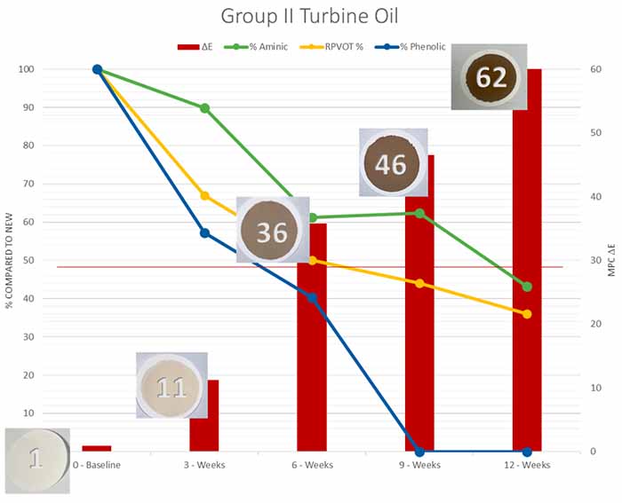
Figure 1: Results of a typical Group II turbine oil in a TOPP test. Under these test conditions, the primary characteristics that change in a turbine oil are antioxidant depletion, resulting in a reduction in oxidative stability and the formation of deposits.
An Oil-related, Catastrophic Failure Mode in Some Gas Turbines
A rare yet severe failure mode linked to turbine oil degradation has been observed in industrial gas turbines. This issue arises when the antioxidants within the turbine oil are exhausted, yet the oil continues to be used.
The situation becomes critical when an additional catalytic factor contributes to the chemical reaction. Under these conditions, the oil may undergo a process known as condensation polymerization, leading to the formation of long-chain cyclic compounds enriched with esters and acidic components.
The consequence of this chemical change in the oil is a dramatically accelerated degradation rate, which can be identified by increased deposits and an exponential rise in viscosity and acidity.
For the turbine, this scenario typically results in bearing failure and coating all oil-wetted components within the system with a highly adhesive and tenacious deposit. This deposit can significantly impair the turbine’s performance and necessitate extensive maintenance or repairs.
An example of trend analysis from this failure mode can be viewed in Figure 2.
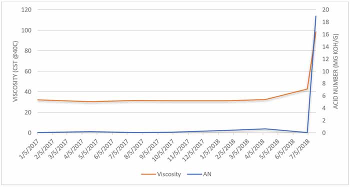
Figure 2: Rapid, catastrophic failure of a turbine due to a simultaneous event of the oil running without antioxidants and a coolant leak. One can observe the viscosity increase to 100°cSt @40C for a month and the acid number increasing to almost 20.
Sensor Selection
The market offers diverse sensor technologies, each delivering distinct value across different applications. The selection of an appropriate sensor necessitates a thorough analysis of both the lubricant’s failure modes and the operational characteristics of the machine.
It’s important to note that sensor technology may be highly beneficial in one context yet offer minimal value in another.
Consider the following examples:
- Inline Viscosity Sensor: This sensor is particularly valuable in methane screw compressors, where gas ingression can cause rapid decreases in viscosity. In contrast, its utility is limited in turbine applications, where viscosity changes are uncommon. For instance, regarding the oil degradation previously discussed (Fig. 4), monitoring antioxidant health or detecting water ingression would be more predictive measures than tracking viscosity changes.
- Chip Detector: A chip detector can be an early warning indicator of impending engine failure in a fighter jet. However, its value is significantly reduced in steam or gas turbines. Wear metal formation is infrequent in these applications, and installing sensors directly downstream of each bearing for chip detection is logistically complex and often impractical.
Infrared Spectroscopy
The sensor platform developed by Spectrolytic utilizes the powerful analytical technique of mid-infrared spectroscopy to measure various relevant degradation parameters in an oil sample.
With each measurement, the sensor determines the changes in the oil at a molecular level using the same analytical technique and data extraction employed by oil laboratories worldwide.
The laboratories conduct an oil analysis on customer samples by applying various ASTM and/or DIN standards to determine Oxidation, Nitration, Sulphation, additive changes, and oil contamination levels.
This common baseline of using mid-infrared spectroscopy as the analytical tool not only allows the sensor to provide real-time data with the same units and accuracy as the oil laboratories, but it also provides the option to predict more complex oil parameters such as Total Acid Numbers (TAN), Total Base numbers (TBN) or ipH.
Another factor that should be considered is the simplicity of generating calibration files for any given oil/application. We have developed and designed the systems to allow the customer to monitor most parametric data from the day of installation.
There is no need to have old oil samples, ship oil samples around the world, or age the oils artificially.
Spectrolytic’s sensor platform has been installed in many different applications such as power generation (natural gas and biogas engines, gas turbines), aluminum and steel processing, and marine application (Marine Diesel and EAL oils for thrusters), showcasing the versatility and accuracy of the mid-infrared sensor platform.
Figures 3 and 4 compare lab analysis and inline sensor data for a natural gas engine application. There is an excellent agreement between predicted sensor data and reference analysis, as shown in the plots below.
The plot also displays ‘rogue’ measurements from reference analysis that the sensor does not display. This is likely some error in sample taking or sample measurement.
The sensor, therefore, removes all human involvement from the oil analysis process as there is no sample-taking process, no storage/shipment required, and no lab technician needed to carry out the measurements.
The results are reliable and consistent with the reference analysis, providing customers with accurate, understandable, and actionable oil analysis data 24/7.
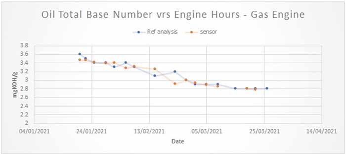
Figure 3: Comparison of Total Base Number determined by Spectrolytic’s online midinfrared sensor and sample data sent to a laboratory.
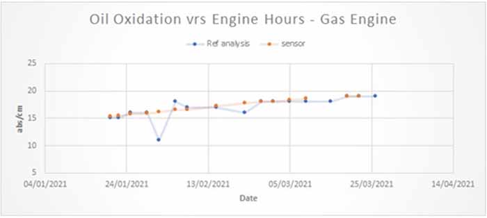
Figure 4: Comparison of Oxidation determined by Spectrolytic’s online midinfrared sensor and sample data sent to a laboratory.
Today’s oil formulations are complex and depend primarily on the application (engine, hydraulic, gearbox, etc.) regarding the base oil and additive packages used.
Base oils from Group I-III are mineral oils (even though some Group III base oils are classed in terminology as ‘synthetic’), and Group IV (PolyAlphaOelfins) and Group V (PolyAlkyGylcol, Polyolesters, Phosphate Ester, siloxanes, etc.) are classed as synthetic oils.
Multiple degradation mechanisms happen in parallel once a lubricant is used in an application. Turbine oil degradation is depicted below in Figure 8.
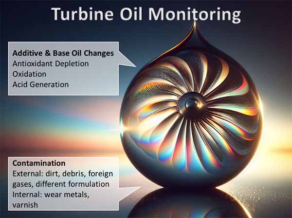
Figure 5: The key parameters requiring measurement and trending in turbine applications.
For any sensor technology to provide accurate, meaningful, and actionable data, the respective sensor technology must be able to DIFFERENTIATE between the respective degradation mechanisms. It must be able to QUANTIFY each degradation mechanism.
Spectrolytic took on this challenge with the development of its FluidinspectIR™ product line. It is now possible to offer customers real-time oil analysis with lab-quality data. A summary of the oil degradation parameters that are accessible using the FluidinspectIR ™ product line is presented in Figure 6.
Apart from these more conventional parameters, it is often also possible to measure parameters that are not commonly reported in a conventional oil analysis report but might provide an interesting insight into a specific application.
One example is the emulsifier absorption by the lubrication gear oil following a water leak during steel production.
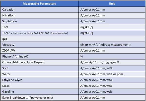
Figure 6: Potential parameters that can be measured using Spectrolytics mid-infrared sensor technology and the units the results are reported in.
The FluidinspectIR™ sensor platform can be complemented with additional sensors, such as viscosity, optical particle counting, etc., to provide customers with a complete solution for their respective applications.
Turbine Application Case Studies
The following shows where a FluidInspectIR™ system has been installed on a gas turbine in Figure 10. Field results from this application over the last nine months show lab results that are indistinguishable from real-time sensor results.
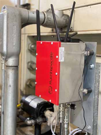
Figure 7: FluidInspectIR platform installed on a Solar Turbine gas turbine package.
In this instance, the customer aimed to track not only phenols, amines, and oxidation levels in their oil but also the concentration of Solvancer™, a product used to enhance solubility and provide long-term protection against varnish.
Figure 8 illustrates that the average Solvancer level is maintained at around 3.09%, with the ability to detect changes as small as 100ppm. The Solvancer concentration must be held at a specific concentration over time, and it is crucial to monitor this level accurately during the turbine’s operation.
The FluidinspectIR sensor monitors the overall oil condition remotely and can identify any changes in concentration, such as when new oil is added to the system.
The fresh oil would dilute the Solvancer, resulting in a noticeable decrease in its percentage, potentially accelerating the varnish production processes of the lubricant. Based on the observed drop in the Solvencer concentration, the customer can be advised to top up the required concentration to retain optimum lubricant protection.
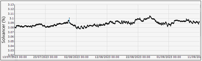
Figure 8: Trend of Solvancer content showing an average of 3.09%.
The most innovative aspect enabled by accurate, lab-quality real-time data for turbine and/or other asset management applications is “The Power of Slopes.”
The FluidinspectIR provides a complete oil analysis every hour, which enables us to analyze the slopes for any given parameter rather than look at the absolute values, which is the status quo, using conventional oil analysis.
An example of a brand-new diesel engine that suffered extensive soot generation during operation is shown below. After 200 hours, the customer decided to change a crucial component in the engine, which was the suspected root cause of the soot problem.
At the same time (220h), the oil was also changed, as is evident by the drop in oxidation (red circle at the bottom image).
Comparing the slopes of the soot graph before and after the maintenance process, it is evident that the root cause of the problem was not the suspected part, as the slopes are identical. The sensor data provided this information after 40 operational hours.
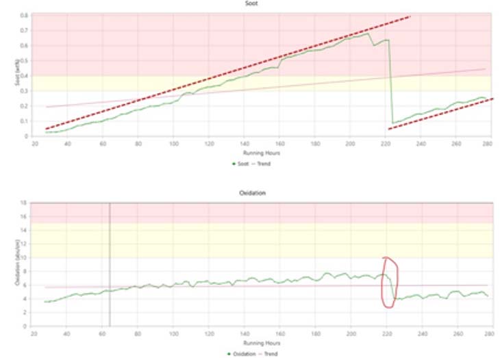
Figure 9: Demonstration of the “Power of Slopes”
The same approach is now being employed in turbine oils. Figure 13 displays a pattern where the oxidation rate in the turbine oil progressively increases across three oil change events. This trend could indicate a shift in the turbine operation or duty cycle.
However, it is more probable that the oxidation rate increased due to insufficient cleaning of the lubrication system between each oil change. Typically, the lifespan of oil is reduced by half if the cleaning between oil changes is not thorough, and the data presented in Figure 9 aligns with this understanding.
In the same way, the sensor data can now be used to ensure that any potential adverse effects related to an oil change are minimized, as the changes in the slopes will be evident even after a few days of operation.
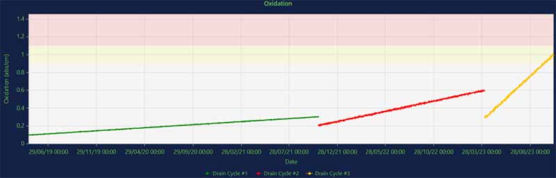
Figure 10: Changes in the rate of oxidation from one oil change to the next.
Figure 11 illustrates a noticeable shift in the oil’s concentrations of phenols and amines. The in-service oil was a phenol-only formulation. However, the graph shows a significant decrease in phenol levels coinciding with a marked rise in amine levels.
This suggests that a new formulation, different from the original phenol-only composition, was introduced into the oil. This change can serve as an alert, allowing for a prompt investigation to confirm whether the addition was deliberate and whether the new formulation is compatible with the existing system.
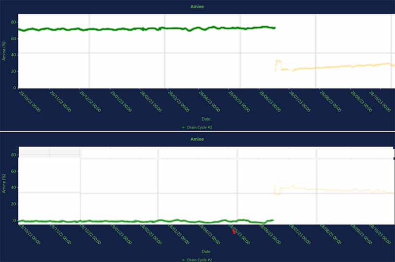
Figure 11: A step decrease in phenols occurring at the same time as a step increase in amines means a different formulation was added to the in-service oil.
Almost every turbine component is monitored in real-time, except for its lubricating oil. As the operational conditions of rotating equipment and turbomachinery evolve, there’s a reduction in on-site resources to support traditional lab-based condition monitoring.
This contrasts with the growing desire of central turbine engineers to get instant overviews of their entire fleet’s performance. These trends highlight the ever-increasing necessity for sensors that can provide real-time monitoring of the oil’s condition.
The first step in choosing a suitable sensor involves understanding the machinery’s and oil’s potential failure modes. For rotating equipment, the main concern is bearing health, particularly the oil’s tendency to form varnish.
Key changes to monitor in the oil include the depletion of antioxidants, corresponding reduction in oxidation stability, and an increase in oxidation, which leads to a higher potential for varnish formation.
Currently, mid-infrared technology is the only sensor capable of measuring these crucial failure modes. Notably, the data quality from these sensors matches that of laboratory tests, eliminating the need for new correlation studies to interpret the sensor data.
Spectrolytic’s FluidInspectIR has been effectively implemented in turbine settings, showing significant potential in fulfilling the increasing demand for accurate, affordable, real-time monitoring of some of the world’s most critical assets.
References
[1] Kazempour-Liasi, H., Shafiei, A. & Lalegani, Z. Failure Analysis of First and Second Stage Gas Turbine Blades. J Fail. Anal. and Preven. 19, 1673–1682 (2019). https://doi.org/10.1007/s11668-019-00764-1
[2] “Steam-turbine diaphragm repair strategies” https://www.ccj-online.com/steam-turbine-diaphragm-repair-strategies/
[3] John K. Whalen, Thomas D Hess Jr, Jim Allen, Jack Craighton. Babbitted bearing health assessment, Middle East Turbomachinery Symposium 2015.
[4] Mathura, S. “Lubrication Degradation Mechanisms (Reliability, Maintenance, and Safety Engineering),” CRC Press, 2020
[5] Livingstone, G., Rista, E. “How to Select Turbine Oils Strategically for Improved Results Now,” https://precisionlubrication.com/articles/select-turbine-oils/