In Part 1 of this series we talked about the evolution of rolling element bearing life calculations from the original work of Lundberg and Palmgren in the 1940s and 50’s to the most recent ISO 281 standard, published in 2007.
Central to the ISO 281:2007 standard is the concept that bearing life is inextricably linked to both bearing metallurgy and lubricant film thickness through the introduction of the term Kappa, defined as the ratio of the viscosity of the lubricant in use at operating temperature versus the minimum viscosity required to support the dynamic load on the bearing (Figure 1).
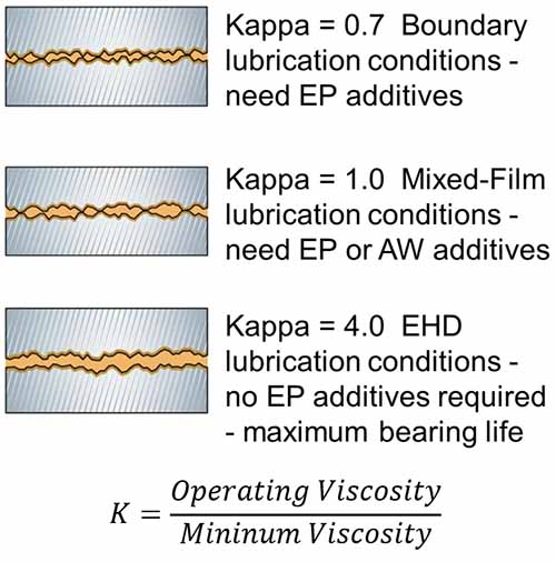
Figure 1: Impact of Kappa on oil film thickness
Based on the ISO281:2007 standard, optimum bearing life can be achieved as Kappa approaches 4.0. But, while this may seem intuitive based on the definition of Kappa, in practical terms, how do we choose a lubricant to achieve the desired film thickness?
How to Optimize Kappa
Regarding optimizing Kappa, bearing manufacturers have made our job relatively straightforward. The first step is to know the minimum viscosity (Vmin) requirements for the bearing under operating conditions.
This can easily be calculated from the bearing dimensions or, more specifically, the mean pitch diameter and the rotational speed using formulae provided in the ISO 281:2007 standard (Figure 2).
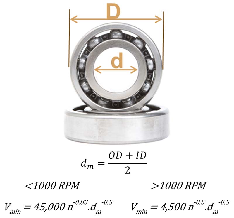
Figure 2: Calculating the minimum viscosity requirements for a rolling element bearing
Mean pitch diameter (dm) is simply the average of the bearing outside diameter (OD) and inside diameter (ID). It represents the bearing diameter at the centerline of the rolling elements, while n is rotational speed under normal operating conditions. Plugging dm and n into the equations shown in Figure 2 yields the minimum viscosity required to separate the moving surfaces of the bearing.
While the equations in Figure 2 can be used to calculate Vmin, most bearing manufacturers provide a simple nomograph method such as the one shown in Figure 3 (Ref: SKF) to estimate Vmin. In this example, for a bearing with a mean pitch diameter of 400 mm rotating at 500 RPM, the minimum viscosity can be determined to be 10 cSt simply by looking at the intercept between pitch diameter and rotational speed.
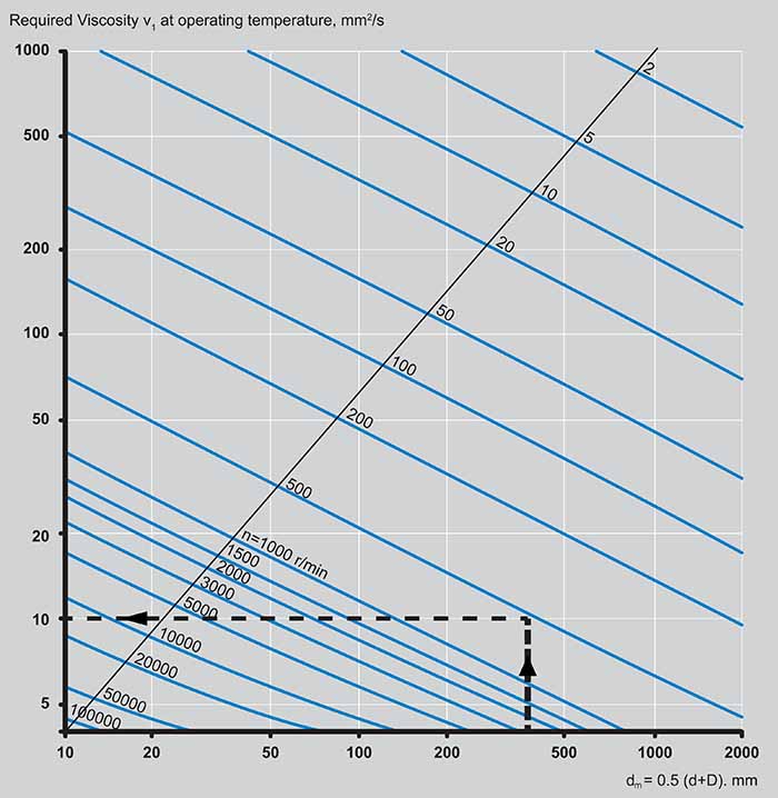
Figure 3: Minimum Viscosity Selection Nomograph
By definition, selecting a lubricant that has the same viscosity as the calculated minimum Vmin will yield a Kappa value of 1.0, far below our desired 2.0-4.0 range. Vmin should be considered the minimum, not the optimum viscosity.
Step 2 of the process requires that we evaluate our options for which lubricant we use and specifically what the lubricant’s viscosity will be at typical operating temperatures so that we can choose an appropriate lubricant to achieve a Kappa in the 2.0 – 4.0 range.
For lubricating oils, this is relatively straightforward based on the oil’s kinematic viscosity and viscosity index, typically provided on the manufacturer’s product datasheet (PDS).
However, care must be exercised for grease since we need to know the viscosity of the base oil contained within the grease, which should not be confused with the thickness of the grease, as given by the NLGI number. Both the NLGI number and the kinematic viscosity and viscosity index of the base oil within the grease are always provided in the grease PDS.
The base oil’s kinematic viscosity and viscosity index can be used to calculate the lubricant’s viscosity at the known or estimated operating temperature using a standard viscosity-temperature graph as given in ASTM D341. To choose the correct base oil viscosity to provide a Kappa of 4.0, we need to multiply Vmin by four, then draw a horizontal line at that viscosity (Figure 4).
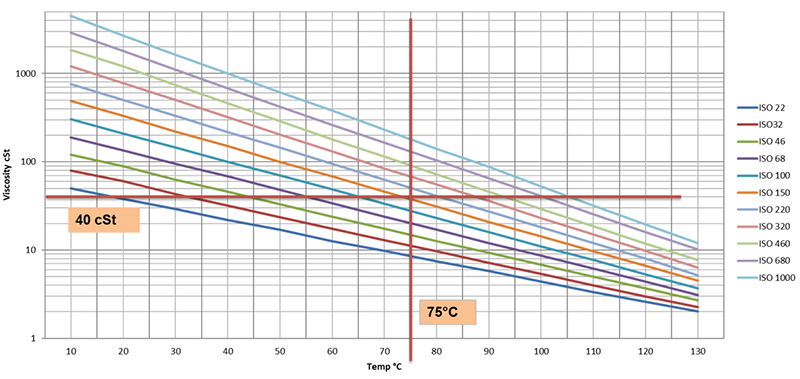
Figure 4: Viscosity selection to achieve an operating viscosity of 40 cSt
In the example shown in Figures 3 and 4, for a Vmin of 10 cSt (Figure 3), a Kappa of 4.0 can be achieved by selecting a lubricant with a viscosity at an operating temperature of 40 cSt. If the operating temperature is estimated to be 75° C (168° F), the correct choice would be a lubricant with an ISO viscosity grade of 150 (Figure 4).
In some circumstances, such as very slow turning or heavily loaded applications, selecting the viscosity to yield a Kappa greater than 1.0 may not be possible since the fluidity of the lubricant would not permit effective oil distribution or grease to the bearing.
Where a Kappa value greater than 2.0 cannot be achieved, wear-preventing additives should be used. For Kappa values between 0.8-1.5, antiwear (AW) additives should be used, while if Kappa is less than 0.7, extreme pressure (EP) additives should be used.
Bearing Lubricant Volume
Aside from selecting the correct viscosity, ensuring that the bearing receives enough lubricant is also critical. While this is not specifically included in the ISO 281:2007 standard, it goes without saying that using the correct amount of oil or grease significantly impacts bearing life, which is why bearing manufacturers provide robust guidelines for proper lubricant application.
This is relatively straightforward for oil-lubricated assets, requiring that oil flow rates in the circulating system provide sufficient lubrication or for bath or splash lubricated applications that oil levels are correct to ensure enough oil reaches the load zone of the bearing.
By contrast, grease-lubricated element bearings are notorious for being under or over-lubricated. However, just like lubricant selection, determining the optimum quantity and frequency of grease for an element bearing is relatively simple, requiring us to know just the bearing dimensions and speed of rotation (RPM).
The optimum quantity needed to re-grease a rolling element bearing can then be easily calculated by measuring the OD of the bearing, along with the full width of the bearing, and multiplying by a scalar, either 0.114 if measured in inches or 0.005 if measured by millimeters as shown in Figure 5.
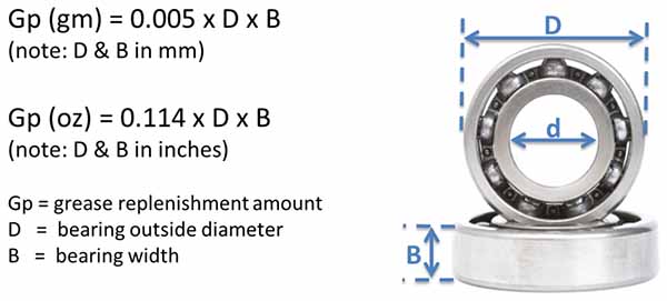
Figure 5: Simplified Method for Calculating Correct Re-grease Volumes
Bearing Re-grease Frequency
There are several methods used to calculate the re-grease frequency. However, the simplest is to use an algorithm first proposed by Canadian Lubrication Engineer Lloyd (Tex) Leugner (Figure 6). This equation which works for moderate to high-speed bearing applications (>100-200 RPM), allows for a simple yet effective means of estimating how frequently grease should be re-applied.
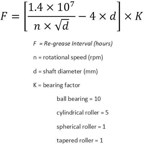
Figure 6: Equation to Determine Optimum Re-grease Interval
The equation in Figure 6 includes a multiplier based on bearing type, which considers shearing action found in more heavily loaded bearings, particularly those that experience axial thrust.
In some circumstances, ambient conditions or operational contexts can reduce the effectiveness of grease lubrication.
This includes mechanical shear stress, bearing (shaft) orientation, heat, particle, and moisture contamination. As such, adjustments to the calculated re-grease interval should be made based on the factors outlined in Figure 7.
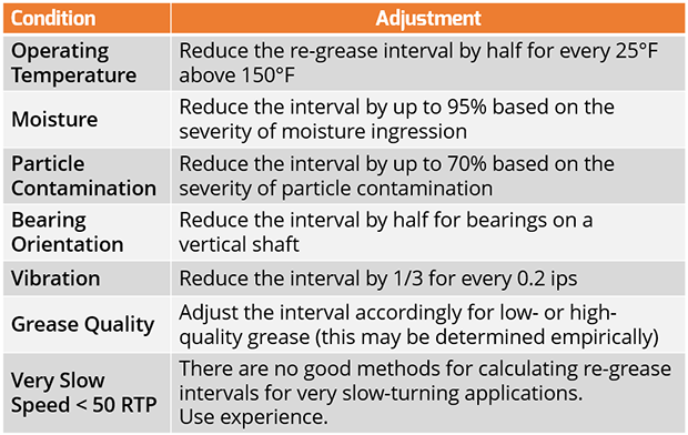
Figure 7: Adjustments to Re-grease Intervals
While calculating the correct quantity and frequency is always advisable, particularly for critical high-speed bearings, significant reliability improvements can be made using a hybrid approach. The calculations above are supplemented by real-time feedback through ultrasound measurement.
These impacts generate ultrasonic energy in the 20-50 kHz range even before significant wear occurs.