I had a laboratory manager, over twenty years ago, complain to me that he wished I would stop pushing particle counting, as he was getting annoyed by clients asking for it after my courses. In his view, particle counting was necessary primarily for hydraulic oils and gas turbine oils. He stressed that PQ readings (ferrous density analysis) were far better than particle counting. Nothing that I could say would ever change his mind.
Admittedly, having been heavily involved in all forms and techniques of particle counting in the past, I may be biased. Still, particle counting plays a role in all forms of machinery for used oil analysis.
So, the question is: how can we ensure the two are used correctly and complement each other?
Predictive or Proactive?
The term Predictive Condition Monitoring is used a lot on LinkedIn to the extent that I begin to wonder whether people really understand that whilst predicting failure is a cost-benefit, preventing failure is essential to achieving reliability and sustainability in a safe and green plant.
A proactive approach considers the root cause of failure rather than simply predicting failure. Solid particles are among the leading causes of failure in most applications and industries. Indeed, this can vary across industries and machine types, where moisture is a significant root cause of contamination.
Understanding Wear Debris Generation
Before we can get into the issue of particle counting versus ferrous density testing, let’s revisit the issue of wear debris generation.
In normal rubbing wear, debris is generally small and low in number.
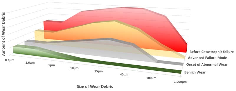
However, as the wear rate increases, the amount of material generated increases, but more importantly, so does the size of the debris.
Particle Counting for a Proactive Approach
Simply put, monitoring particle counts helps identify what’s happening. It’s not quite that simple, however. We need to determine whether the observed trends reflect increased particle ingestion or increased normal wear material.
In the early 1980s, when the ISO 4406 cleanliness code was developed, the idea was that particles larger than 5µm were considered silt, while particles larger than 15µm were considered chips. Silt is generally considered dust particles ingested with normal wear debris. Chips are typically the result of abnormal wear.
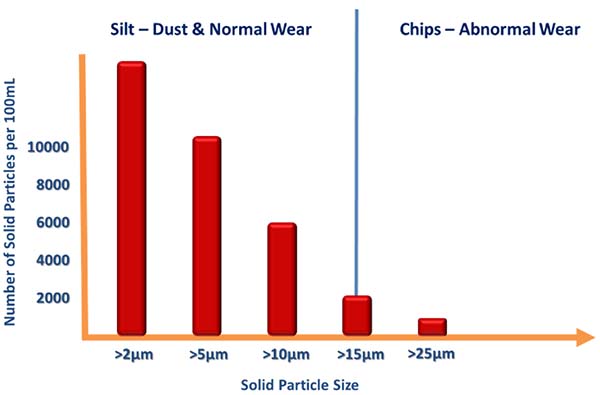
Consequently, a rise in silt is likely due to either increased levels of ingested external solid particulate or increased normal wear, the latter indicating an issue. Either way, both are an alert to a problem.
However, a rise in chips is definitely of concern as that indicates the onset of abnormal wear.
The Limitations of Particle Counting
The reason many commercial laboratories avoid particle counting for machinery other than hydraulics is simple. Most rely on the light obscuration or light scattering particle counters for various reasons, namely:
- Light blockage/light scattering units comply with ISO 11500:2022 – Hydraulic fluid power — Determination of the particulate contamination level of a liquid sample by automatic particle counting using the light-extinction principle” and thus tie in with other compliance requirements.
- They require a small sample volume, typically less than 15mL.
- Bench units are typically automated for high-volume use.
However, the downside is that anything other than relatively clean, dry oil will cause an issue, namely:
- The flow through the sensor is restricted, so large debris could block the device and hold up the testing of samples as it is cleared.
- Water droplets and air bubbles are counted as solids.
- Dark fluids can be difficult for the light to penetrate.
- Soot in engine oils, while technically not counted as per ISO 4406, owing to their tiny size, will cause issues with blinding the sensor.
While the above can be addressed by properly preparing a sample to eliminate air and water, this is time-consuming for a high-turnover laboratory.
Indeed, recent advances in light-blocking technology have reduced the occurrence of water droplets and air bubbles, but this still poses a problem with gear oils in particular, owing to the often-present issue of large debris, even if the water issue has been, or can be, addressed. Note that many industrial gear oils have higher viscosity grades, which would hamper flow through the sensor.
It is easy to see why commercial laboratories would shy away from using gear oils for particle counting, and the same applies to high-soot-load engine oils and to water in the case of steam turbine and paper machine oils.
Hydraulics are perhaps the most sensitive to particle ingress, and, fortuitously, these are typically of lower viscosity grade, are clean and dry, and have significantly less wear debris, which is typically much smaller.
Ferrous Density Analysis Techniques for a Predictive Approach
As the name implies, ferrous density analysis measures the concentration of iron in the oil sample. Unlike spectrographic oil analysis at the elemental or atomic level, it is not limited by debris size. With elemental analysis utilising inductively coupled plasma or arc-spark technology, wear debris particles exceeding 8µm create a blinding spot.
Simply put, the concentration of the atoms on the surface of the debris is detected, but the atoms of the inner body of the larger wear debris are not detected. This has been addressed using X-ray Fluorescence Technology, which is more accurate in this context, but it is not widely used in many laboratories.
In ferrous density analysis, various approaches rely on magnetism or the Hall Effect to determine the result. The three primary techniques are:
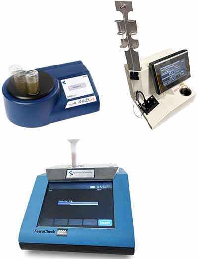
- Particle Quantifier – The ANALEXpql was initially developed by the late Dr. Mervyn Jones of the Swansea Tribology Centre and is now a product in the Parker Hannifin range of instrumentation. Based on Hall Effect measurements, it reports a value on a 0–200 scale, with higher values indicating greater ferrous material in the sample.
- Direct Reading Ferrograph – The Trico DR-7 Direct Reading Ferrograph unit uses a magnetic gradient to trap ferrous debris and measure the amount of small (<5µm) and large (>5µm) debris to provide a Wear Particle Concentration, as well as a Percentage of Large Particles.
- Coil measuring technology – The Spectro-Scientific FerroCheck 2000 utilises a pair of precision, rounded coils that, when powered, generate magnetic fields. When a small amount of in-service oil is introduced into one of the coils, ferrous particles interact with the magnetic field, inducing current changes in the coil. The amount of current change is proportional to the amount of Ferrous particles in the oil and can output a result in parts per million (ppm) as per ASTM D8120-17 Standard Test Method for Ferrous Debris Quantification
- Another approach is that users of portable particle counters have been able to use a strong magnet to separate the Ferrous material from a sample following a particle count, and then repeat the count minus the Ferrous material to see how significant the percentage is. In addition, the trapped Ferrous material is analyzed using a microscope.
- A simple magnetic sump plug or “mag-plug” is a fundamental form of Ferrous density trending; however, a photograph should be taken during inspection to assist with trending the amount of material trapped at each inspection.
In most commercial laboratories, my experience is that the PQ unit is more common outside North America, while the DR unit is more popular in North America.
For more details on the ANALEXpql and FerroCheck 2000, I suggest you also read the excellent article by Bryan Debshaw and David Swanson in Precision Lubrication, “Assessing Spectroscopic Methods to Analyze Particles: PQ vs. FerroQ” – Assessing Spectroscopic Methods to Analyze Particles: PQ vs. FerroQ.
The Limitations of Ferrous Density Testing
By the very nature of relying on magnetism to trap the Ferrous material or measure it via the Hall Effect, then clearly the focus is on Ferrous debris. Moreover, the magnet is more likely to attract the larger material, too.
Consequently, while this approach works well on gearboxes that by their nature generate more wear debris, typically of a Ferrous nature, it is less successful on other machines where the amount generated is significantly less and more varied, with the focus needing to be on the non-Ferrous material.
Unlike the Direct Reading Ferrograph unit, the ANALEXpql cannot differentiate between small and large debris, either. However, there are ways around this by shaking the sample and observing how the PQ reading rate changes. A slow increase in small debris, a rapid increase in larger debris. The actual oil volume and the sample bottle size may also affect the result, so consistency is required to avoid erroneous results.
For most high-volume commercial laboratories, the ANALEXpql and FerroCheck 2000 are better suited in terms of test time and ease of sample preparation.
Particle Counting and Ferrous Density Testing?
Running both particle count and ferrous density tests together will ensure that the full range of particle sizes can be detected and that changes at any size are captured. While elemental analysis is an indicator of the presence of smaller material, it reports only concentration, not the number of particles or their size.
While several laboratories will simply not accommodate that request for both techniques, the use of a portable particle counter, such as the Pall PCM500 unit that uses mesh blockage, as this, while not conforming to the ISO 11500, does not suffer from the problems of dark, high viscosity oils contaminated with larger wear debris or water.
Similarly, these units are not affected by high soot loading on engine oils. The Pall instrument is ideally suited to on-site use; however, most laboratories do not use this method because it is technically classified as a trending device rather than a counting device per ISO, and it requires a sample volume of over 200mL.
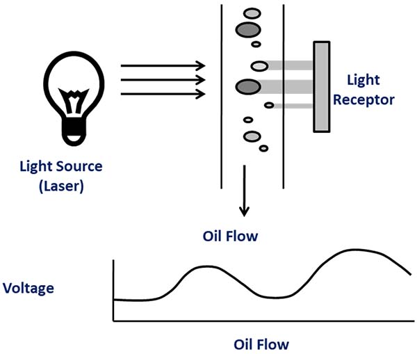
In the last decade, the Laser Net Fines unit has proven effective, offering both particle counting and a breakdown of wear debris by wear mechanism, while also differentiating water and air in the sample. It complies with ASTM D7596 – Standard Test Method for Automatic Particle Counting and Particle Shape Classification of Oils Using a Direct Imaging Integrated Tester.
In Summary
Whichever way you choose to approach this, remember that particle counting provides insight into what is happening within the machine based on the size and number of solids, and enables proactive intervention to prevent failure. Wear debris is the result of a root cause issue, whether that be looseness, misalignment, imbalance, or a lubricant-related cause.
Ferrous density testing is a reliable indicator of increasing ferrous material levels. Sadly, for most end-users, and given how their oil analysis programmes are set up and managed, the data is often seen too late. The problem results in downtime and machine intervention rather than a proactive correction during machinery uptime.