
Understanding Electrostatic Spark Discharge and Its Impact on Lubrication Systems
Electrostatic Spark Discharge typically occurs when static is built up in an oil at a molecular level, causing it to discharge in the system and create free radicals, which increase the opportunity for varnish to form. This usually occurs at temperatures of around 10,000 °C.
If we were to liken this to an everyday situation, we could think about walking around a carpeted room where the static builds up in our body. When we touch a metallic object (more than likely a door handle), we get a bit of a shock as the built-up static is discharged through us and the door handle.
Inside a lubricant system, static doesn’t just build – it ignites microscopic sparks powerful enough to scar filters and start the chain reaction that leads to varnish.
Similarly, in lubricants, static exists at a molecular level, and in areas of tighter clearances, some molecules are forced to rub against each other, causing a buildup of static. When it accumulates to the point of becoming a full charge, it dissipates at the first opportunity, usually at the filter membrane or some sharp-edged object along the way. These are seen as burnt patches on the filter membrane.
When this spark occurs, it creates a chemical reaction that generates free radicals. Free radicals are highly reactive species that need to engage with other substances. These are the initiators of varnish, and their presence can accelerate reactions, leading to deposits forming in the lubricant. Eventually, this will lead to a system that has experienced both ESD and oxidation.
In this article, we will discuss various identification methods and ways to prevent ESD in modern lubrication systems. We will also spend some time identifying typical root causes for ESD by developing a logic tree as a guide for future investigations.
How to Identify Electrostatic Spark Discharge in Lubrication Systems
Every degradation mechanism produces varying results in the form of deposits or in how these are formed. For ESD, some tell-tale signs alert the user to its occurrence. These include:
- Crackling sounds / buzzing outside of components – This noise is representative of sparks as they discharge on part of the media/asset. Typically, this occurs when the fluid is in motion, allowing it to be heard near the filters when the system is operating.
- Burnt or pinhole filter membrane – The filters usually feel the full effect of ESD, and small burn patches or even pinholes are created when ESD occurs. When changing filters, the membranes should be examined for these patches to determine if ESD is occurring.
Free radicals are produced when ESD occurs. As such, this leads to polymerization of the lubricant, which produces varnish and sludge. This is part of the oxidation process, and the antioxidant levels will begin to decrease. During ESD, certain gases are also released in the oil. Some of the lab tests which can be used for identifying where ESD has occurred include:
- RULER® – Remaining Useful Life Evaluation Routine test, which quantifies the presence of antioxidants in the oil. By trending this over time, one will be able to determine whether the levels of antioxidants are decreasing or not. Typically, this test can be performed twice annually on larger sumps (such as turbines) or the frequency can be increased according to the criticality of the equipment. If the value gets below 25% then this is the critical limit, and methods to regenerate the oil or change it should be explored.
- MPC – Membrane Patch Colorimetry – this measures the potential of the oil to form varnish or deposits. Depending on the equipment, the warning limits will vary, but a good rule of thumb is to treat results below 10 as normal, those above 15 as within the monitor range, and those above 20-25 as the critical range. Be sure to double-check these levels with the OEM of the equipment.
- FTIR – Fourier Transform Infrared Spectroscopy can identify various molecules in the oil. It is likened to identifying the fingerprint of the oil, where each molecule has a specific characteristic spectra representative of that molecule. This test can be used to identify the presence of oxidation or any deposits that may have formed.
- DGA – Dissolved Gas Analysis – this test can be used to identify the presence of particular gases that are released during ESD, such as acetylene, ethylene, and methane.
Those above are just some of the methods that can be used to identify the presence of ESD in a lubrication system.
Effective Strategies to Prevent ESD in Lubrication
ESD occurs when there is a buildup of static in the oil; therefore, one of the best methods of preventing it is to ensure that the static levels remain low or are dissipated before they have a chance to wreak havoc on the system. The simplest and most common way of reducing this static is the installation of antistatic filters. These filters can help to remove static from the system before it builds up to dangerous levels, where it can burn the membranes or develop varnish.
Static in oil is inevitable – how you control and discharge it determines whether your system runs clean or burns itself from within.
Ensuring that the system is grounded correctly is another way to guarantee that any built-up static is removed. This is where your electricians can perform checks and install proper grounding devices for your equipment to safeguard against this buildup of static in the system. Therefore, if static charges get built up in the system, they can be dissipated without the effects of ESD.
If oils experience high levels of conductivity, they can conduct static. Typically, if the conductivity is above 100pS/m, there is potential for the fluid to conduct the charge and allow it to be discharged along the system without causing harm.
Unfortunately, there are base oils with low conductivity (below 100pS/m) that cannot carry the charge and dissipate more easily. As such, these types of oils will see an increase in the presence of ESD if not formulated correctly for modern lubrication systems.
As the viscosity of the oil decreases, more force is required to pass through the filters, which can lead to a buildup of static at a molecular level. Additionally, as temperatures decrease, the viscosity also decreases. In these cases, keeping the oil at the system temperature (designed for that particular viscosity) can help to reduce the buildup of static charge in the oil.
Identifying the Root Causes
Thus far, all the prevention methods have focused on the physical roots of ESD. We did not explore some of the human or systemic roots that are also accountable for ESD. In this section, we will develop a logic tree designed to address a critical failure occurring in a plant. This will be used as an example of the logic tree, which can be developed when investigating the root causes of ESD.
Let’s start with the top of the logic tree, where we define the event or the reason we care. In this situation, it is an unplanned shutdown for 4 hours. An unplanned shutdown will impact the plant’s production, which is why we care about conducting this investigation.
We will assume that the failure mode occurred on one of the critical pumps, and we are investigating how that failure could have happened. Note, we did not ask the question “Why?” because it can be misleading to an opinion, and we are trying to stay as factual as possible.
A disciplined root cause analysis doesn’t start with ‘why’ – it starts with evidence. Each degradation mechanism tells its own story, and Electrostatic Spark Discharge is just one of them.
For this investigation, we will investigate the hypothesis of a critical bearing failing due to lubricant degradation. Since we are focused on ESD for this article, we will have only one hypothesis regarding the degradation mode being ESD. However, in the real world, if this logic tree were being developed, we would be investigating the six various lubricant degradation mechanisms: oxidation, thermal degradation, microdieseling, ESD, additive depletion, and contamination.
As shown in Figure 1, at the top of the logic tree, we start by placing our hypotheses on the tree, and then using evidence/facts, we can rule them out afterwards. This is a critical step as the investigation should be able to stand on its own in the court of law (even if it may not reach that point). The next hypothesis is the buildup of static in the oil. There are three possible ways for this to occur;
- Clearances too tight (as discussed earlier, this can lead to molecular friction, which can induce static)
- Less than adequate grounding system (if a proper grounding system doesn’t exist, then there isn’t an option for the static to dissipate)
- Less than adequate conductivity of the oil (if the conductivity of the oil is too low, then the charge can build up and cause it to be dissipated along the system, such as the filters)
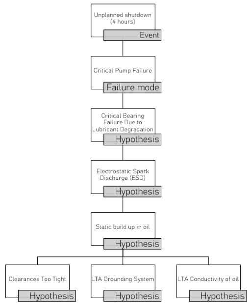
Figure 1: Top part of the Logic tree for ESD
Now, we need to investigate each of the three main hypotheses stated and find out the root causes for them.
Let’s begin with the Clearances being too tight hypothesis.
For this hypothesis, we will ask the question, “How can clearances be too tight?”. In this case (and we will have to keep it general and in broad buckets, so we can drill down into these later and eliminate as necessary), there are three possible reasons:
- The OEM could have designed the system such that it was less than adequate (LTA)
- The flow rate could have been increased above the recommended threshold
- Incorrect viscosity of the lubricant could cause additional friction (we will dive into this one later).
We will develop the other two hypotheses in Figure 2.
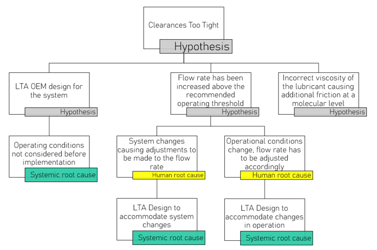
Figure 2: Investigating the hypothesis, “Clearances too tight”
If we further investigate where the OEM did not design the system effectively, we can determine that the operating conditions were probably not adequately considered before implementation. This is a systemic root cause and one that needs to be addressed with the OEM.
On the other hand, if we investigated the flow rate, there could be two main reasons for the adjustment. One could be because of system changes, which forced adjustments to the flow rate. Since a decision was made here, it is a human root cause. Someone decided to change the flow rate based on the variables involved. However, if we investigate why these changes were made (once a human is involved, the question moves from how to why), we can determine that the system was not designed to accommodate these changes. This is a systemic root.
Similarly, if the operational conditions change (such as when a higher output is required, which is different from system changes), then the flow rate must be adjusted. Again, a decision must be made here, and a human is involved. Then we ask the question, “Why?”. In this case, we have the same systemic root, and the design is inadequate to accommodate the necessary changes.
For this part of the tree, we have found some human root causes where decisions were made, as well as systemic root causes. Both need to be addressed when we perform the final root cause analysis. For the human root causes, we can think about the procedures that guided them to make those decisions (if they existed) and amend these accordingly.
On to the next hypothesis, which we have yet to investigate (still under the clearances being too tight), the incorrect viscosity of the lubricant, which is shown in Figure 3. There are a couple of ways in which this can happen:
- OEM recommendations were not followed
- There was an unavailability of the specified viscosity of the lubricant
- There was a less-than-adequate procedure for selecting the correct viscosity of lubricant
If we investigate why the OEM recommendations were not followed, we can find two main reasons. Either they were not documented and therefore could not be followed, or the internal best practice was used instead to replace the OEM recommendations. In both cases, these would be systemic root causes, and we should investigate why these were not documented or why they were replaced.
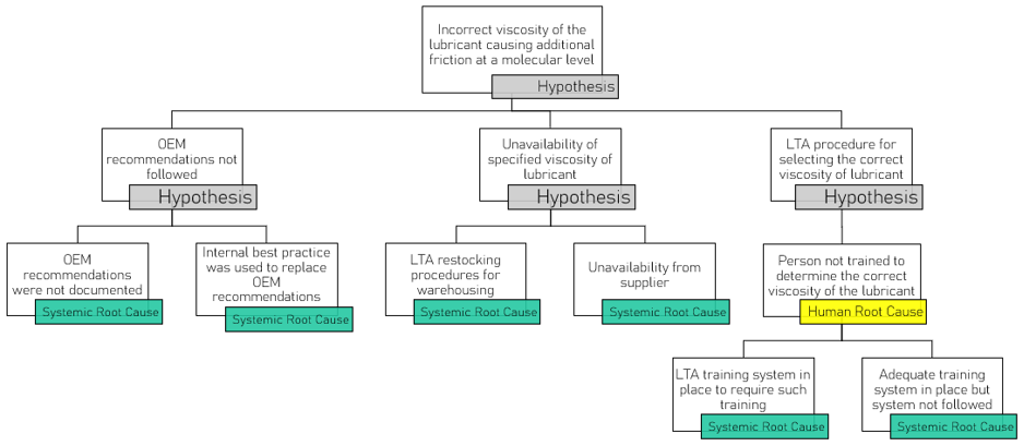
Figure 3: Investigating the hypothesis, “Incorrect viscosity of lubricant”
When investigating the unavailability of the specified viscosity of the lubricant, we can find two main causes. Either there was an issue with the restocking of this lubricant at the warehouse due to their forecasting, or appropriate checks were not carried out. This is a systemic root cause that should be investigated further.
Another hypothesis could be that the specified lubricant was unavailable from the supplier. This is another systemic root cause and should be addressed with the supplier to ensure it is resolved in the future.
When lubricant viscosity errors trace back to missing stock or missing training, the problem isn’t the person or the product – it’s the system that allowed both to fail.
On the other hand, if we examine the procedure for selecting the correct viscosity of the lubricant, we identify a human root cause, as someone would have made the decision on which viscosity to use. But in this case, we need to investigate why the person was not trained to determine this value.
There are two main reasons why a person does not receive training: either it doesn’t exist, or it was not followed. In both cases, these are systemic roots that need to be further investigated and addressed.
Now, we will investigate the next major hypothesis, “LTA grounding of the system” in Figure 4.
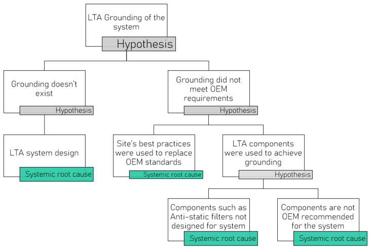
Figure 4: Investigating the hypothesis, “LTA Grounding of the system”
When investigating the grounding of a system, we can identify two major classes: either it doesn’t exist, or it didn’t meet the requirements. If grounding did not exist, then this is an inadequate system design and therefore a systemic root cause. On the other hand, if the grounding did not meet the OEM requirements, we need to determine how this was possible.
There are two possibilities: the site’s best practices were used to replace the OEM standards, which is something we often see, especially if these requirements have worked in the past. This is a systemic root cause that should be investigated. Or there were fewer than adequate components to achieve grounding.
In this case, we can have components that are not designed for the system (do not meet the system’s requirements) or components that were not OEM-recommended and are being used (such as aftermarket products that do not meet the necessary specifications).
Finally, on to the last major hypothesis, “LTA conductivity of the oil,” as shown in Figure 5.
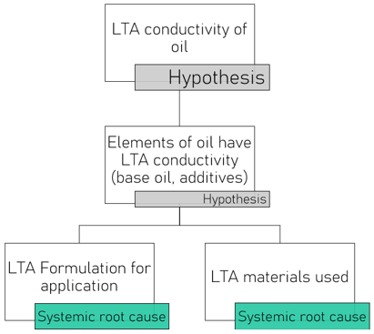
Figure 5: Investigation of the hypothesis, “LTA Conductivity of oil”
Figure 5: Investigation of the hypothesis, “LTA Conductivity of oil”
As noted earlier, if an oil has a conductivity of more than 100pS/m, it will be able to dissipate any accumulated charge easily. However, if it falls below this value, the charge will be dissipated in the system at the earliest opportunity.
How can oil have less than adequate conductivity? Perhaps the elements of the oil have a less-than-adequate conductivity. If that is the case, then there can be two plausible reasons for this. Either the formulation was not appropriately designed, or the materials (base oils, additives) were not of a particular standard. Both causes are systemic root causes and should be investigated further to determine if anything can be done to correct these.
If we were to summarize a list of the root causes, we would see that many are systemic, while a few are human, as shown in Figure 6.
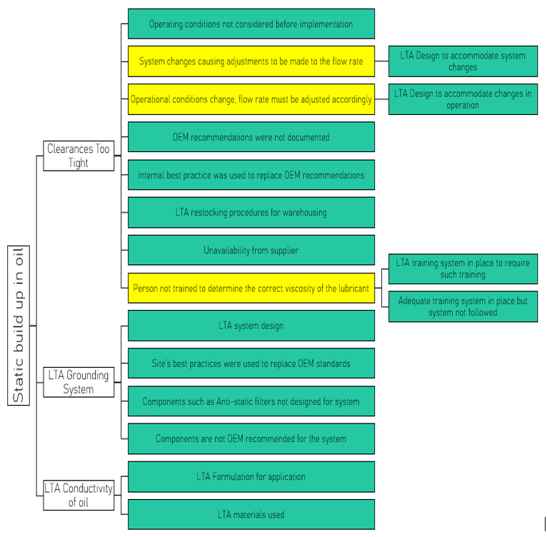
Figure 6: Summary of the root causes of ESD
This further reiterates the need to develop a comprehensive logic tree when investigating any failure, as many root causes are not physical or surface-level. If these are not adequately addressed, the failure mode will recur in the future. The entire logic tree can be found here under additional support material, along with logic trees for other degradation mechanisms.
References
Mathura, S. (2020). Lubrication Degradation Mechanisms: A Complete Guide. Boca Raton: CRC Press.
Mathura, S., & Latino, R. (2021). Lubrication Degradation: Getting into the Root Causes. Boca Raton: CRC Press.