All machines with moving parts have bearings of some type. The bearings may be as simple as flat surfaces working against other flat surfaces, such as the slideway in a machine tool, or they may have sophisticated geometries like a ball screw. Plain and element bearings supporting rotating shafts are found in nearly every machine type you might imagine.
Machine designers use sophisticated tools and techniques to create element and plain bearings that provide a specific function for the machine within which they are found.
This article provides reliability engineers and managers with simple but dependable guidelines for selecting lubricants with the correct chemical and viscometric qualities necessary for long-term reliable operation.
Different Bearing Types and Their Roles in Machine Reliability
Element bearings could be categorized by the function they are designed to provide. Assuming that the shaft’s axis is parallel to the ground, some bearings offer support for shafts with only radial (up and clown directional) load, while others provide support for both radial and axial (side-to-side directional) load.
Figure 1 shows the types and shapes of five common element bearings.
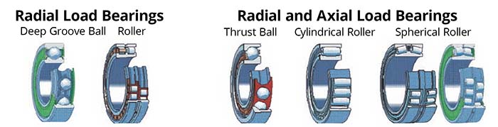
Figure 1 – Types and Shapes of Five Common Element Bearings (Courtesy of Lubcan, Inc.)
Roller bearings and deep groove ball bearings have elements shaped to support a load that is primarily in one direction perpendicular to the axis of the shaft.
Comparing the shape of the inner and outer rings (races) for the deep groove ball bearings to that of the thrust ball bearings, one can see from the difference in curvature of the race contact area around the ball (element) that the thrust ball type of bearing should be capable of with standing more axial force than the deep groove bearing.
Figure 2 shows the orientation of the force relative to the shape of the race in a radial thrust bearing. All bearings are designed by the designer to accommodate a given type (direction) and amount of thrust.
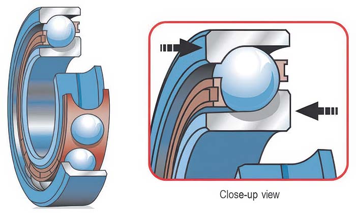
Figure 2 – Direction of Applied Force for Thrust Ball Type Bearing
The OEM is responsible for installing the bearing into the machine in the proper orientation. In some instances the machine designer may choose to specify two thrust ball bearings with their respective thrust orientation turned opposite to one another to support a shaft with a load that moves back and forth.
The machine builder may select bearings designed to accommodate force in both directions for machines that operate with a significant amount of directional force along one or more shafts.
An increase in element surface area increases the load potential for the element bearing.
Cylindrical and spherical roller bearings are designed to support shafts with both radial and axial (directional) forces. Again, comparing the differences in the shapes of the elements and the races, one can see how the shape of the element conforms to the shape of the race, accommodating thrust from one or both directions.
One may also observe a large difference in the amount of contact surface areas between the races and elements of the deep groove ball bearing and the thrust and roller bearings. An increase in element surface area increases the load potential for the element bearing.
How Oil Films Protect and Extend Bearing Life
The type of oil film produced by mechanical components in dynamic interaction is dictated by the kind of surface interaction that the components experience.
Element bearings exhibit rolling contact characteristics and are characterized as forming and operating in EHD film conditions. EHD films are exceedingly thin, ranging between one-half and one-and-one-half microns thick. To put this into perspective, there are 25.4 microns in 1/1,000th of an inch.
Figure 3 provides an array of commonly recognized items categorized by their respective micron dimension. The dimensions of the oil film thicknesses representative of the EHD film are on par with the dimensions of a bacteria.
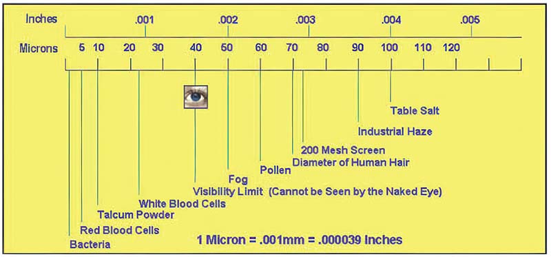
Figure 3 – Micron Dimensions of Commonly Recognized Items (Courtesy of Schroeder Filter Corp.)
Despite the thinness of the EHD film condition, a properly established oil firm demonstrates remarkable durability when the lubricant is maintained in a healthy, clean, dry state.
The dynamic thickness of the EHD film is influenced by many design parameters, including:
- Bearing material hardness
- Material pliability
- Dynamic loading
- Dynamic temperature
- Contact surface area
- The lubricant pressure viscosity response (pressure viscosity coefficient)
- The initial oil viscosity
- Other parameters
A properly established oil film demonstrates remarkable durability when the lubricant is maintained in a healthy, clean, dry state.
In the selection process, the reliability engineer is keenly interested in ensuring that the selected lubricant meets the minimum acceptable operating limit to achieve an EHD film condition. The reliability engineer can do so by systematically following a few key principles and establishing an acceptable operating viscosity.
How to Select the Optimal Viscosity for Element Bearings
The most critical characteristic to establish is the lubricant’s viscosity at operating temperature. Viscosity changes with temperature and pressure. As temperature increases, viscosity decreases, and viscosity increases as pressure increases. These factors are interdependent.
The most critical characteristic to establish is the lubricant’s viscosity at operating temperature.
The pressure viscosity relationship depends on the type of raw materials used to construct the lubricant. For any given lubricant selection, the reliability engineer cannot change this characteristic, so we will focus on selecting the correct oil thickness regardless of the type of lubricant.
The central questions for selecting the correct lubricant grade for a given brand and product type are:
- What will the lubricant’s viscosity be at the normalized machine operating temperature?
- What are the allowable, minimum, and optimum viscosities for a given element bearing regardless of operating temperature?
The first question begs for knowledge of the machine’s operating state. Machine speed, load, process temperatures, oil viscosity, and frictional conditions at the element contact area influence temperature. If the machine is already in operation, then the answer may be evident from machine observation and measurement. If not, the reliability engineer must consult with the OEM and production personnel and collect sufficient information to project a safe answer.
For this exercise, assume that the temperature is known; we’ll use a figure of 154°F (70°C). We will also assume the shaft speed is 2,000 RPM, and the bearing has been properly selected for the application.
An exact number can be produced if every incremental de tail is known (speeds, loads, forces, material compositions and strengths, VP responses, etc.). As most plant circumstances afford only estimates of these details, this article provides a model that can be followed by plant personnel to appropriately answer questions without the requirement for a full set of exact details and a computer-aided design program.
Step 1
Locate a viscosity selection reference chart for element bearings. Fortunately, most bearing manufacturers provide suitable tables and charts in their lubrication reference guidebooks. Figure 4 is provided by FAG Bearings and is appropriate for this task1.
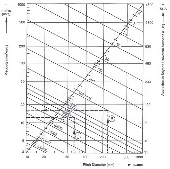
Figure 4 – Viscosity Selection Chart (Courtesy of FAG Bearings)
Step 2
Use the following formula to estimate bearing pitch diameter, d111, where:
Dm = (OD + ID)/2
OD = Bearing Outer Diameter
ID = Bearing Bore
Assuming you wish to lubricate the bearings in a 254-frame-size motor containing bearings with a bore diameter (ID) of 45 mm and an outer diameter (OD) of 85 mm, the pitch diameter is 65 mm, locate this value on the chart’s x-axis (bottom of the chart), and plot a vertical line from this point to the top of the chart.
This line is referenced on the chart as item I.
Step 3
Determine shaft rotation speed (noted above as 2,000 RPM). Locate the diagonal line labeled with this value on the chart.
Step 4
Using a chart similar to the one in Figure 4, locate the intersection of the pitch diameter and shaft speed lines.
Step 5
Draw a line from this intersecting point to the left side of the chart, to the y-axis, to read the mini mum allowable viscosity in centistokes (mm2/sec).
Following these instructions, these points coincide on the y-axis at approximately 12 centistokes. This value represents the bearing manufacturer’s projected minimum operating viscosity or the required oil thickness at the normal machine operating temperature. It is advisable to try to provide three to four times this value as a target operating viscosity.
The practitioner must still determine which of the available grade options will deliver this result.
Step 6
Determine the correct starting viscosity (always measured at 40°C), as noted above. After observing the following steps, the practitioner may use Figure 5 to determine the viscosity starting point (viscosity value at 40°C)2.
Step 6 (a)
Determine the target viscosity (three times the required viscosity= 12 cSt * 3 = 36 cSt). Locate this viscosity value on the y-axis. Plot a line parallel to the x-axis (left to right) from this point.
Step 6 (b)
Locate the machine operating temperature on the x-axis. From this point, plot a line parallel to the y-axis (bottom to top).
Step 6(c)
Note where the two lines intersect. If the value is not at a normal ISO code specification, select the viscosity grade representing the next highest category. This chart represents paraffinic mineral oils with a viscosity index of around 100.
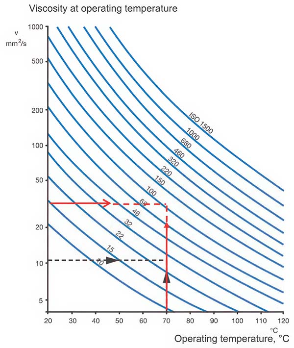
Figure 5 – Viscosity Temperature Chart (Courtesy of SKF Bearings)
The black arrows in Figure 5 represent the minimum recommended operating viscosity parameters, and the red lines provide parameters to meet the preferred operating viscosity. A lubricant with a viscosity grade above ISO 100 and below ISO 150 would be appropriate.
Given that it is an electric motor bearing on a small frame-size motor that is nearly always grease lubricated, one should look for grease constructed with a viscosity grade at or slightly above 100 centistokes.
Choosing the Right Additives for Bearing Lubricants
The minimum allowable viscosity estimated for the conditions is expected to maintain a ‘fat’ (EHD) oil film in an element bearing. EHD conditions provide for complete separation of interfacing surfaces, but the separation ranges from a paltry 0.5 to 1.5 microns for ball and roller-type bearings.
Within this range (one-time minimum allowable limit), manufacturers suggest the use of rust and oxidation-fortified (R&O) mineral oils and greases containing these types of fortified oils.
Some bearing manufacturers and recognized authorities propose that wear-resistant (AW) and seizure-resistant (EP) additives should be incorporated to protect surfaces3 if the film ratio falls below the minimum allowable level.
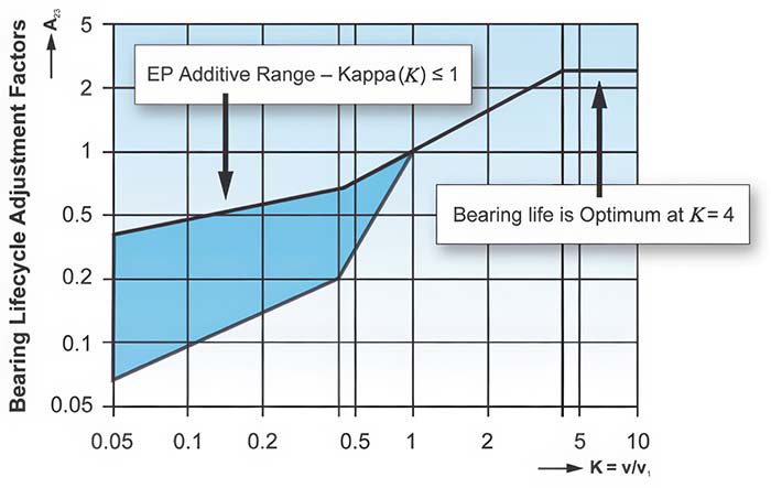
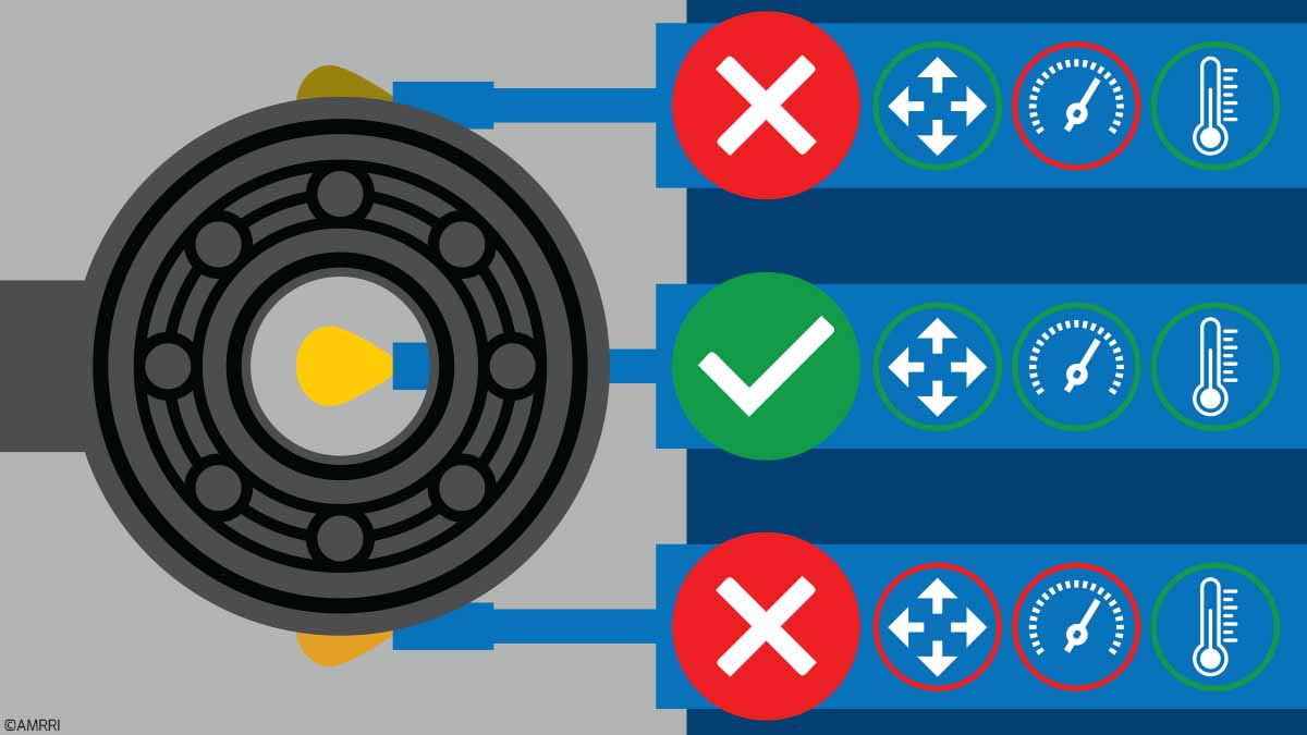
Figure 6 – Using Kappa to Refine Additive Type Selection
It is possible to estimate whether a given bearing in a given set of conditions requires an EP-fortified oil or grease through a film thickness ratio K, or Kappa factor. This is the ratio of the proposed viscosity (at operating temperature) divided by the bearing manufacturers’ required minimum viscosity (at operating temperature).
A ratio of 3 is optimum, so a value of three times the allowable minimum was recommended during Step 6(a). Figure 6 shows a viscosity ratio range for which EP additives are highly recommended.
Choosing the correct oil viscosity can significantly impact bearing life and overall machine reliability.
A manufacturer’s general-purpose (GP) greases commonly have viscosities between 100 cSt and 220 cSt, even though most element-bearing applications carry minimum requirements in the 12 to 22 cSt range.
For very slow-moving and heavily loaded element bearings, it is appropriate to select even higher-viscosity oils and greases and incorporate solid-film agents for enhanced protection against shock loading and loss of EHD condition. Remember that thicker oils and grease consistencies tend to churn, generate heat, and consume energy, particularly in moderate to high-speed applications.
Element bearings are manufactured in a variety of sizes and configurations. Ball bearings have lower contact areas than thrust bearings, but bearings with higher contact areas can support greater loads. Element bearings have definable minimum allowable viscosity limits.
A reliability engineer may use a relatively simple approach to verify that the correct viscosities have been selected. Viscosities should be optimized to a level at least three times greater than the allowable minimum. Bearings that operate with viscosities below the recommended mini mum limit should incorporate wear and seizure-resistant additives (AW/EP).
References
- FAG Roller Bearing Lubrication Guideline WL81115E.
- SKF Corp. Bearing Maintenance and Installation Guide, p. 29. February 1992.
- Moller, Boor. Lubricants in Operation, p. 116.