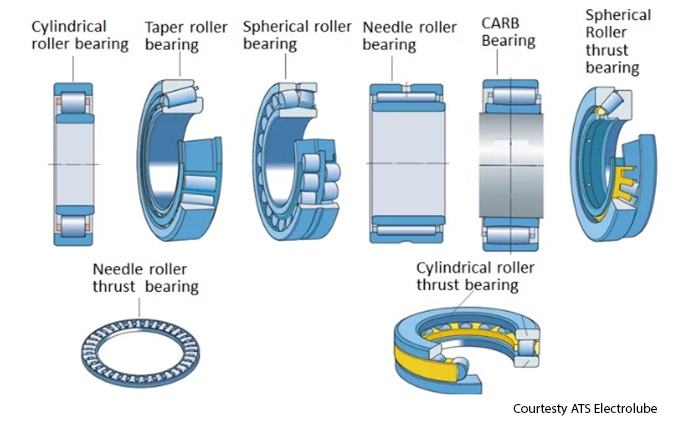
We often get questions during our training courses about lubricant selection. I was recently asked how bearing bore size impact grease selection. Let’s start with defining the type of bearing. There are element bearings that come with a variety of element shapes, sizes, and names.
There are cylindrical rollers, taper rollers, spherical rollers and several different kinds of element shapes. The shape fundamentally defines how often you will lubricate, but not necessarily what lubricant is the best fit.
To determine which lubricant to use, whether oil or grease, you need to understand the bearings parts and how the parts influence this decision.
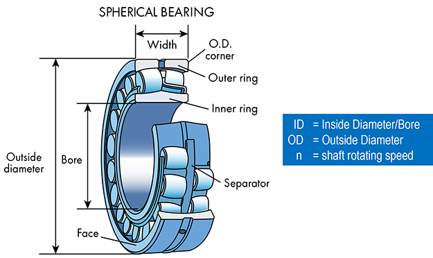
Bearing manufacturer handbooks will identify the point between the 12 o’clock position to the 6 o’clock position on the outer ring (outside the bearing) as the outer diameter (OD). Likewise, the manufacturer will refer to the gap between the 12 o’clock position to the 6: o’clock position inside the inner ring as the bore or Inside Diameter (ID). The axial face plane from one side to the other side of the bearing is referred to as the width. All these dimensions are generally considered in millimeters, and they all come into play when deciding which lubricants to use.
The remaining variable is the speed the shaft is turning. The speed is referred to with an ‘n’ value in most machine maintenance and reliability calculations.
The lubricant selected must contain oil (whether oil or grease) that moves proportionally to the speed that the machine parts move. Machines with fast-moving parts require fast-moving oil and machines with slow-moving parts require slow-moving oil.
When making a bearing lubricant selection decision, the first task is to determine whether or not the bearing is moving at a speed where grease can be an acceptable option. The bearing manufacturers give us that target range (a speed limit value) for the use of grease.
First, we must calculate the nDm value where:
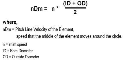
The nDm value gives us an idea of what the angular velocity characteristic is for this bearing. It is used to compare to standardized unit values from the bearing manufacturer to determine whether grease is a good fit.
The chart below shows some suggested limits for four different types of bearings. Generally, the more element-to-race contact and the greater the axial loading characteristics based on bearing design, the less effective grease is going to be. Determine whether it is safe to lubricate with grease before going to the next step.
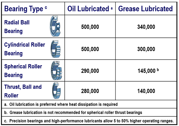
Note: These parameters reflect concern over grease stability more than bearing construction. Borderline values are not absolute. If an element is operating above the noted speed limit it will require more frequent lubrication to maintain long-term reliability.
Once you determine whether grease or oil should be used, the next step is to identify the viscosity that is required and the operating temperature to make the elements in the rotating shaft float in the race.
The viscosity of the lubricant at operating temperature is the single most important characteristic to establish.
Viscosity changes with temperature and pressure. As temperature increases, viscosity decreases, and as pressure increases, viscosity increases. These factors are interdependent.
The pressure viscosity relationship is dependent on the type of raw materials used to construct the lubricant. For any given lubricant selection, this characteristic cannot be changed by the reliability engineer, so you should focus on the process of selecting the correct oil thickness regardless of the type of lubricant.
The central questions for selecting the correct lubricant grade for a given brand and product type are:
- What will the viscosity of the lubricant be at the normalized machine operating temperature?
- What are the allowable, minimum, and optimum viscosities for a given element bearing regardless of operating temperature?
The first question begs for knowledge of the machine’s operating state. Temperature is influenced by machine speed, machine load, process temperatures, oil viscosity, and frictional conditions at the element contact area.
If the machine is already in operation, then the answer may be evident from machine observation and measurement. If not, the reliability engineer must consult with the OEM and production personnel and collect sufficient information to project a safe answer to the question.
For this exercise assume that the temperature is known; we’ll use a figure of 154 F (70 C). We will also assume the shaft speed is 2,000 RPM and the bearing has been properly selected for the application.
An exact number can be produced if every incremental detail is known (speeds, loads, forces, material compositions and strengths, VP responses, etc.). As most plant circumstances afford only estimates of these details, this article provides a model that can be followed by plant personnel to appropriately answer questions without the requirement for a full set of exact details and a computer-aided design program.
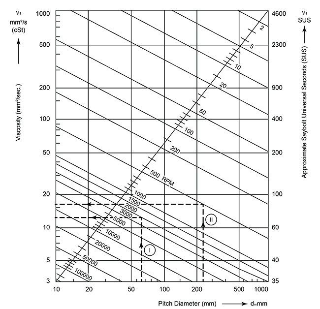
Step 1. Locate a viscosity selection reference chart for element bearings. Fortunately, most bearing manufacturers provide suitable tables and charts in their respective lubrication reference guidebooks. This viscosity selection chart is provided by FAG Bearings and is appropriate for this task.
Step 2. Use the following formula to estimate bearing pitch diameter, dm, where:
- dm = (OD + ID)/2
- OD = Bearing Outer Diameter
- ID = Bearing Bore
Assuming you wish to lubricate the bearings in a 254-frame-size motor containing bearings with a bore diameter (ID) of 45 mm and an outer diameter (OD) of 85 mm, the pitch diameter is 65 mm. Locate this value on the chart’s x-axis (bottom of the chart) and plot a vertical line from this point to the top of the chart.
This line is referenced on the chart above as item I.
Step 3. Determine shaft rotation speed (noted above as 2,000 RPM). Locate the diagonal line labeled with this value on the chart.
Step 4. Using a chart like the one in Figure 4, locate the intersection of the pitch diameter and shaft speed lines.
Step 5. Draw a line from this intersecting point to the left side of the chart, to the y-axis, to read the minimum allowable viscosity in centistokes (mm2/sec).
Following these instructions, these points coincide on the y-axis at approximately 12 centistokes. This value represents the bearing manufacturer’s projected minimum operating viscosity or the required oil thickness at the normal machine operating temperature. It is advisable to try to provide three to four times this value as a target operating viscosity.
The practitioner must still determine which of the available grade options will deliver this result.
Step 6. Determine the correct starting viscosity (always measured at 40 C) in a similar manner as noted above. Observing the following steps, the practitioner may use Figure 5 to determine the viscosity starting point (viscosity value at 40 C)2.
Step 6(a). Determine the target viscosity (three times the required viscosity = 12 cSt * 3 = 36 cSt). Locate this viscosity value on the y-axis. From this point, plot a line that is parallel to the x-axis (left to right).
Step 6(b). Locate the machine operating temperature on the x-axis. From this point, plot a line parallel to the y-axis (bottom to top).
Step 6(c). Note where the two lines intersect. If the value is not at a normal ISO code specification, select the viscosity grade representing the next highest category. This chart represents paraffinic mineral oils with a viscosity index of around 100.
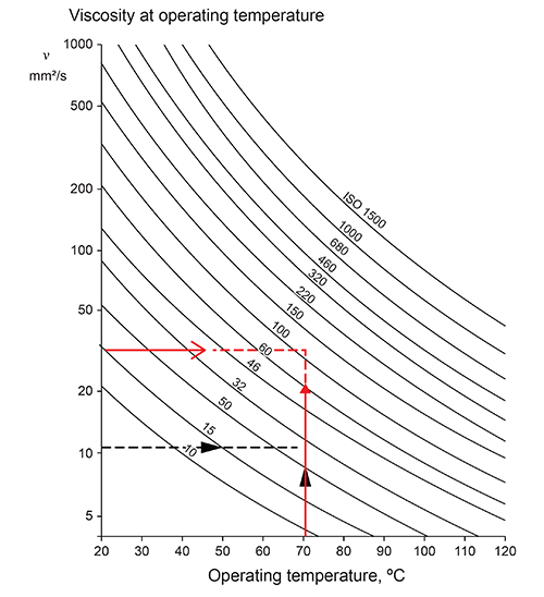
The black arrows in the chart above (courtesy of SKF) represent the parameters to meet the minimum recommended operating viscosity, and the red lines provide parameters to meet the preferred operating viscosity. In this instance, a lubricant with a viscosity grade above ISO 100 and below ISO 150 would be appropriate.
Given that it is an electric motor bearing on a small frame-size motor, and given that these are nearly always grease lubricated, one should look for a grease constructed with a viscosity grade at or slightly above 100 centistokes.
So, as it turns out, the bearing bore size is a key element of lubricant selection decisions, as well as volume and grease replenishment decisions, but it is not the ONLY factor. The bore and the bearing outer diameter are proportionally interrelated, and both of these values are required (along with the bearing width) to answer the key questions related to lubricant selection and daily essential care.