Lubricant management could mean different things to different people within a facility. The maintenance planner or lube crew supervisor may view lubricant management as the process that assures all the machines scheduled for level checks, replenishment, and oil changes are serviced promptly.
The condition control technician may view this as sample collection for analysis and long-term planning. Each would be correct. This article addresses another aspect of reliability-centered lubrication: sump condition control for static sumps.
Non-Circulating Oil Sumps
A non-circulating or static sump is one where the lubricant remains with the components. The lubricant certainly moves around the components under protection.
In this instance, the static sump is one where the lubricant remains with the sump during operation, in contrast to the dynamic sump, where the lubricant drains or is pumped out of the fixture holding the components and is later returned.
A non-circulating or static sump is one where the lubricant remains with the components.
Static sumps for industrial machines are simple enclosures surrounding moving components. Equipment owners typically do not specify standards for seals, filters, heat limits, moisture control, sump volumes, or port dimensions and locations when bidding for simple machines with small sumps.
Consequently, simple assemblies like gear drives and bearing enclosures tend to be exposed to the environment through open vent ports and shaft seals. Machines with complex designs or operational parameters tend to incorporate forced circulation and supply in the design details and suffer less from incomplete design.
It is common to have high criticality rankings assigned to static sumps. It is common for these sumps to build up particularly high contamination loads. Unless effort is applied to controlling contaminant exposure, the associated components will have shortened lifecycles.
Controlling Lubricant Health
Much research suggests that many common wear problems are associated with overall lubricant condition and cleanliness. Oil- and grease-lubricated machines that operate with continuous environmental challenges and without the benefit of sump health controls experience short lifecycles and high repair costs.
Contamination control may be the single largest area for improvements from the implementation of precision lubrication practices.
Contaminants Reviewed
Industrial sites are ripe with contamination sources. The most common problems come from the air we breathe—moisture, particulate, heat, and the air itself.
Temperature changes occurring with normal ambient temperature differences or with normal operating cycles cause the machine to breathe. Although the movement is slight, contaminants from the air settle into the oil and remain until forcibly removed or drained from the sump.
The resident contaminant load can become significant through daily thermal cycles over an extended period. Unfortunately, because the failure modes are slow, it is difficult to see the damage caused by most contaminants until well past an appropriate time to act.
Let’s look at these sources more closely.
Moisture
Water contamination is the fuel that propels oil and machine destruction. Moisture accelerates wear through corrosion from direct contact with surfaces and chemical changes in the oil (particularly for AW and EP oils), increasing the risk of film collapsing under load. Condensation can form on the underside of tank lids, create rust, and thereby add to solid contaminant loads. Moisture also promotes vaporous cavitation and destruction of pump surfaces.
Particulate
Particles promote micropitting, fatigue, and three-body wear in proportion to their concentration in the oil. The solid particle sizes that impose the greatest threat to machine surfaces—small enough to get between the surfaces and bridge the oil film gap—are well below that which can be seen without a microscope.
Additionally, particles become more challenging to crush as their size decreases. Particles that are one to three microns in size are particularly tough and particularly destructive to machine surfaces.
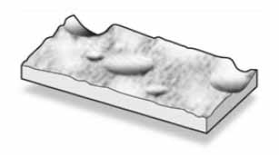
Figure 1. Surface damage typical from wear debris.
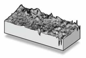
Figure 2. Surface damage is typical of atmospheric debris.
Figures 1 and 2 depict the impact of contaminants on machine surfaces, denoted by whether they are particulate from machine wear (Figure 1) or atmospheric dust (Figure 2). Atmospheric dust can change the machine component’s surface profile if the particle’s hardness exceeds the component steel’s.
Silica-laden atmospheric dust can have a greater hardness rating than many machine steels. When dust particles fracture to a size small enough to enter the dynamic clearances (± 2 microns) at component contact interfaces, these hard, tough particles can cause jagged indentions in the surface profiles.
Wear debris particles existing at the higher particle counts mean higher wear rates—for all types of lubricated components. As wear increases, the catalytic effect of iron and copper debris accelerates chemical reactions and increases the rate of aging.
Air
Air provides oxygen, the other fuel that promotes chemical reactions and drives aging. About 10% of the volume of a container of oil is dissolved air. This is a natural state tolerated in formulation decisions but problematic in higher percentages.
Air entrainment or saturation can occur in static systems when the level is too high or too low when the lubricant is contaminated by water and process chemicals, or when there is a consequence of lost air removal additives.
Heat
Excess heat makes all of the previously noted problems bigger. The Arrhenius rate rule in organic chemistry shows that chemical reaction rates double with each 10°C temperature increase. Following that logic, the aging process increases as sump temperatures increase, doubling with each 10°C increase.
Heat is also added from surface friction, cavitation, and shear stress on the oil film as it thickens under pressure.
Preventing Contamination
With small sumps, prevention is much easier than removal. Prevention of contaminant ingression for pumps, small drives, bearing housings, and other low-volume sumps revolves around exclusion at the shaft seal points vent ports and cleaning the lubricant handling and top-up activities.
Vent Port Improvements
OEM-provided vent filters are typically not designed to arrest airborne contaminants. Vent covers are constructed from metal mesh. Even a 200-mesh screen, considered high quality, is porous, limiting particles that are 75 microns and greater. Covered screens may slow ingression from blowing wind and rain but not extensively.
Upgrades to vent ports are simple and low-cost. Vents should be upgraded to desiccant vent filters where machines operate near high humidity (70% relative humidity or greater).
The dominant suppliers provide models that incorporate high-quality (≥ 5-micron target size) media at the point of air entrance to increase the value of a desiccant element purchase.
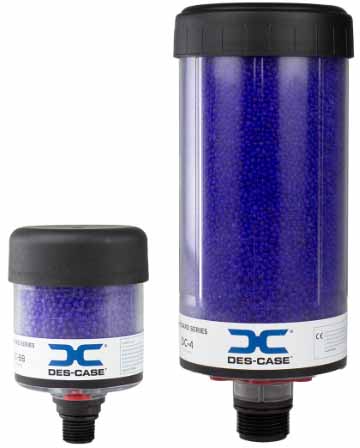
Figure 3. Desiccant elements can arrest airborne contaminant ingress relatively cheaply. (Courtesy of DES-CASE.)
Low-humidity applications would benefit from retrofitting to either desiccant or non-desiccant type elements. Still, the reliability engineer should be conscious of selecting an element that provides a dramatic improvement from the status quo.
Automotive oil filter elements target relatively large particles (β 35 = 90) and are not the best choice for production machines’ oil filtration. However, these elements ported to allow bi-directional air movement provide adequate capture effectiveness for low-particle velocity airflow.
It is a long-standing failure of machine design strategies to place open pipes or screens at vent port locations. The relative cost to close this point of intrusion could run as high as a couple hundred dollars per machine for the initial installation (including labor) and another hundred dollars per year for replacements if high-quality desiccant elements are used. The benefit of extended component and lubricant lifecycles can easily outweigh the cost.
Shaft Seal Improvements
Shaft seal points represent likely points for solid and moisture contaminant ingression. Figure 4 depicts a typical lip seal configuration. Lip seals have a contact fit with the shaft and, by design, are pressed against the shaft during operation.
The subtle movement of the seal from normal radial contact with the shaft causes the seal to flex slightly to perform a slight pumping motion. Lip seals are intended primarily to hold in the lubricant.
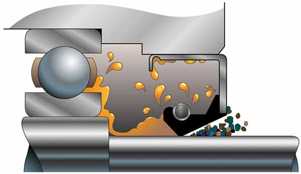
Figure 4. Heat, solid contaminants, and rubbing contact degrade lip seals.
Seal longevity is directly influenced by heat, solid contaminants at the shaft-to-seal interface, and chemical attack due to normal lubricant leaching effects. If operating in climate-controlled conditions, such as a clean room condition required for the manufacture of computer chips, the simple lip seal may function for several thousand hours.
Sumps operating within high contaminant areas can experience loss of seal integrity in a couple of hundred hours.
Bearing isolators significantly reduce the risk of moisture or airborne contamination ingression across the shaft. Bearing isolators maintain a tight fit with the housing and the shaft and only experience rubbing contact between the stator and rotor. This allows for better lubricant sealing and better contaminant prevention.
Lubricant Handling and Top-Up Activities:
Routine lubricant handling practices are an easy third choice for improving lubrication management practices. Lubricants shipped in bulk from the blend plant to a local vendor and then repackaged or sent in a bulk truck to the local customers are subject to tremendous variability in cleanliness quality.
Vessels, including pails, kegs, drums, totes, and bulk trucks, are universally expected to be “clean enough” for end-use, but they are not for many modern manufacturing systems.
The major brands recognize the potential for corruption of the lubricant by the container and have developed rigorous practices for evaluating and condemning questionable containers.
But is that enough?
As it turns out, even following this practice, a high percentage of finished lubricants arrive at the plant site in an unacceptably dirty state for high-criticality machines. This does not suggest that the lubricant pumped into the auger-type trash compactor is too contaminated for safe use.
However, the lubricant intended for the plastic injection molding hydraulic system with pressure-compensated variable volume piston pumps and servo controls operating at 3300 PSI should be serviced before it goes into use.
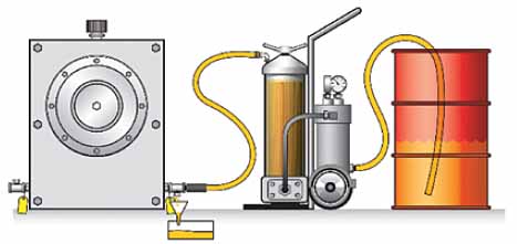
Figure 5. Prefiltering lubricants into a machine sump is a reliability-centered, world-class quality practice.
Preconditioning lubricants before use is simple and relatively inexpensive. Several years ago, world-class manufacturers moved in this direction through simple side-stream filter systems employing high-efficiency, low-particle size media.
Figure 5 illustrates the concept of prefiltering the lubricant as it is being placed into the machine sump. High-capture efficiency elements (βx = 100; = 99%) collect nearly all the targeted particle sizes as the particles enter the element.
Theoretically, some high-efficiency elements remove all but .01% of the particles at and larger than the target particle size. This is immensely beneficial to the machine receiving the lubricant.
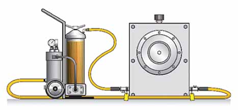
Figure 6. Side-stream filtration is a practice designed to clean the lubricant while it’s in use.
Following initial fill conditioning, the same system can be used to treat the oil in the machine’s sump while the machine is running. Figure 6 illustrates using the same filter system for long-term improvement of fluid operating conditions.
The same type of device can and should be used to control water. The same approach can control moisture, although specialized vacuum distillation systems are more effective than water-removal element inserts.
Side stream filtration should be scheduled as a routine PM practice for all sumps that have (1.) high-criticality rankings, (2.) a high potential repair charge, (3.) large sump capacity, or (4.) contain components that are sensitive to microscopic contaminants or moisture.
Proactive sump management protects both component and lubricant, extending expected lifecycles. Common contaminants that degrade the lubricant include atmospheric air, moisture, dust, and heat. Vent breathers help prevent much of the contamination from the air.
Replacing lip seals with bearing isolators helps limit ingression across the shaft to housing interfaces. Prefiltration of lubricant is necessary for high-criticality machines. Side-stream filtration should also be used systematically as a machine PM to improve fluid conditions and protect machine health.